
PLC (Programmable Logic Controller)
FULMATIC 7 – PLC Systems
Fulmatic 7 – Series PLCs are the programmable control devices which are designed according to the automation needs by considering the tough conditions of the industry. Fulmatic 7 – Series PLCs are offered with 2 different memory options, 32KB and 115KB. All PLCs include Ethernet, Modbus TCP and minimum 1 RS485 Modbus RTU connection as well as webserver feature. The program can be installed into Fulmatic 7 PLCs in RUN state, it doesn’t requires switching to STOP state.
-
- FULMATIC 7 PLC
-

- PLC CPU 202F
-
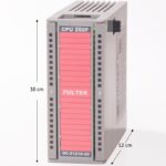
- Size
-
- IO Capacity
Features:
- The program can be installed while the PLC is running.
- The reasons for swithching the PLC to STOP state are monitored in the diagnostics section.
- High accuracy RTC(Real time clock) is standard for all models. It also works 30 days without energy supply. Battery does not used so it does not requires replacing the battery.
- The entire PLC memory can be used as ladder code or as persistent variables. You can use the 117760 Byte or 58880 Word variable in a single PLC.
- With additional modules, the 8192 Digital input or 512 analog input can also be extended to 8192 digital outputs or 512 analog outputs.
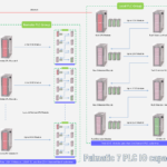
- Thanks to its rack structure, 63 additional modules can be added to the PLC. 4 racks can be made with rack connection module.
- Up to 32 Remote IO Cpu modules can be expanded. 4 racks can be added to each Remote IO Cpu module.
- The maximum number of modules available in a rack is 16. When 1024 modules are used, the PLC cycle time will still be below 5 milliseconds.
- With the Remote IO Cpu, remote IO modules can be controlled. Remote IO Cpu can be operate on Rs485 or Ethernet.
- Single PLC can respond to 17 devices simultaneously as 5 Modbus Tcp/Ip, 2 Modbus Rtu and 10 web client. At the same time, each device can read/write up to 256 bytes long data 60 times per second. The total duration of the query/response is about 16 milliseconds. At this time, the PLC cycle time will still be less than one millisecond.
- With a single PLC, 256 automatic PID and 256 PWM control can be made. In addition, with the 8-channel Motion module, 256 of 100 KHz PW or PTO outputs can be used in the single PLC.
- There are 256 software counter commands in one PLC. In addition, with the 8 channel counter(Motion) module, 256 units of 100 KHz counters can be used in single PLC.
- A single PLC has 256 timers with a resolution of 1 millisecond. The time-based interrupt block allows you to create thousands of software-based timers.
- You can create 256 program blocks and 256 function blocks in one PLC. Each block can have 32 networks. You can write 256 commands to each network.
- Function blocks can work with a pre-loaded parameter. For example, you can prepare a function block for motor control and call this block differently for thousands of motors. For each call, you just need to assign the variables of the respective motor.
- You can create 255 Data blocks in a single PLC. A data block can have a maximum length of 1024 bytes. DB0 is a 1024 byte length system data block. The first 345 bytes are used by the system. The other 679 Bytes are dedicated to your use. Program installation, PLC reset, firmware update or any other way DB0 is never deleted.
- The powerful Ladder compiler will compile almost any code you prepare. Restrictive situations do not occur, such as simple PLCs, such that input is not available after an output or output on each line.
- You can monitor the energy flow and variable values very quickly in the online ladder block monitoring screen. From this screen you can change the values of the variables.
- All models have 512Kb webserver space. All kinds of files can be stored in this field. You can also use the PLC program to store the user manual or project images. You can access it encrypted and unencrypted. Files uploaded to the Webserver will only be stored in the PLC and no other servers are needed. Clients over the local network or the Internet can access these files. You can upload large image files to different servers for using webserver’s memory efficiently.
- The hardware and safety features of the Fulmatic 7 Series PLCs are also at the highest level. All terminal connectors are protected. If 220-380 volts are not delivered incorrectly, the PLC will not be damaged. With 24 Volt you can connect all input outputs upside down, straight, short circuit or all other ways. Most will not work. You can even select analog inputs as 0-10 volts and use them as digital inputs with 24 volts. When 0-20 Ma is selected, the protection will be activated.
- Fulmatic 7 PLCs are capable of updating firmware via ethernet. In this way, you can get benefits of all updates. As with some PLCs, you will never see the message “This version cannot program this PLC”. Each update will be available in old PLCs as well.
- Fulmatic 7 PLCs are guaranteed for 2 years. Supply fails at 220 or 380 volts, water exposure or breakage with physical impacts is not covered by the warranty. Apart from these, we will only ask how its failed for improving our measures.
Fulmatic SOFT Plc software is FREE. With the Fulmatic SOFT program you can program Fulmatic 7 PLCs without any restrictions.
| GENERAL FEATURES | Description |
| Supply | 24V DC %15 tolerance band, 2,4W power consumption(standby) |
| Digital Input / Output | Has 8 digital input and 8 digital output. |
| Analog Input / Output | There is a different number of analog inputs and outputs according to the CPU model. |
| RS 485 | According to CPU model, there are 1 or 2 Rs485 port with 1200-230400 bps range. Modbus RTU support. |
| Ethernet | 10/100 MBit Full dublex, DHCP support, WebServer support(10 socket), TCP Modbus support(5 socket), 512KB webserver file space. |
| Program Loop Speed | Maximum loop count 65000 in a second. |
| I/O Capacity | 512 Analog Input and 512 Analog Output or, 8192 Digital Input and 8192 Digital Output |
| RTC | Real Time Clock (Runs 30 days without electricity.) Accuracy 3 seconds / Month @ 25 °C |
| Working Conditions | -20 +60 °C / %5-95 Humidity |
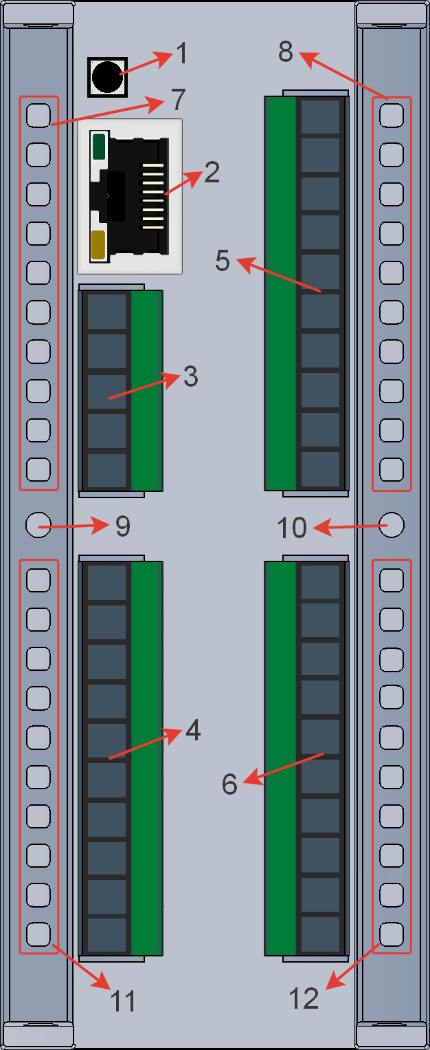
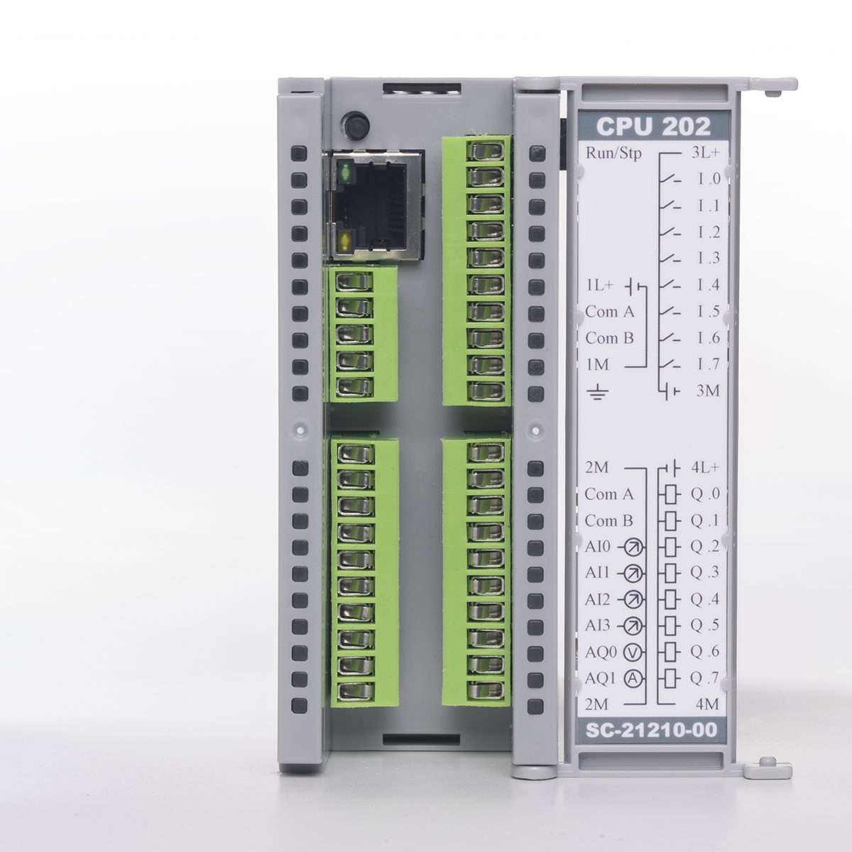
| No | Connection Node | Description | Group No | Connection Node | Description | ||
| 1 | PLC Run/Stop Button | 7 | sA.0 Led Block | 1 | PLC Run Led | ||
| 2 | Ethernet | Soket | 10/100M Fullduplex Ethernet | 2 | Fault Led | ||
| Yeşil Led | Ethernet Link led | 3 | |||||
| Sarı Led | Ethernet Comm. led | 4 | |||||
| 5 | |||||||
| 3 | xA.0 Connection Terminal | 1 | +24V supply node | 6 | |||
| 2 | COM0 RS485 A node | 7 | COM0 TX led | ||||
| 3 | COM0 RS485 B node | 8 | COM0 RX led | ||||
| 4 | 0V supply node | 9 | |||||
| 5 | Ground node | 10 | Power Led | ||||
| 5 | xB.0 Connection Terminal | 1 | +24V terminal supply | 8 | sB.0 Led Block | 1 | RUN Led |
| 2 | I 0.0 input | 2 | I 0.0 input led | ||||
| 3 | I 0.1 input | 3 | I 0.1 input led | ||||
| 4 | I 0.2 input | 4 | I 0.2 input led | ||||
| 5 | I 0.3 input | 5 | I 0.3 input led | ||||
| 6 | I 0.4 input | 6 | I 0.4 input led | ||||
| 7 | I 0.5 input | 7 | I 0.5 input led | ||||
| 8 | I 0.6 input | 8 | I 0.6 input led | ||||
| 9 | I 0.7 input | 9 | I 0.7 input led | ||||
| 10 | 0V terminal supply | 10 | Power Led | ||||
| 6 | xB.1 Connection Terminal | 1 | +24V terminal supply | 12 | sB.1 Led Block | 1 | Power Led |
| 2 | Q 0.0 output | 2 | Q 0.0 outp. led | ||||
| 3 | Q 0.1 output | 3 | Q 0.1 outp. led | ||||
| 4 | Q 0.2 output | 4 | Q 0.2 outp. led | ||||
| 5 | Q 0.3 output | 5 | Q 0.3 outp. led | ||||
| 6 | Q 0.4 output | 6 | Q 0.4 outp. led | ||||
| 7 | Q 0.5 output | 7 | Q 0.5 outp. led | ||||
| 8 | Q 0.6 output | 8 | Q 0.6 outp.led | ||||
| 9 | Q 0.7 output | 9 | Q 0.7 outp. led | ||||
| 10 | 0V terminal supply | 10 | PLC Stop led |
| No | Bağlantı Noktası | Grup 1 | Grup 2 | Grup 3 | Grup No | Bağlantı Noktası | Grup 1 | Grup 2 | Grup 3 | ||
| 4 | xA.1 Connection Terminal | 1 | 0V power | 0V power | 11 | sA.1 led block | 1 | Power led | Power led | ||
| 2 | Analog Input 0 | COM1 RS485 A | 2 | COM1 RS485 TX | |||||||
| 3 | Analog Input 1 | COM1 RS485 B | 3 | COM1 RS485 RX | |||||||
| 4 | Analog Input 2 | Analog Input 0 | 4 | ||||||||
| 5 | Analog Input 3 | Analog Input 1 | 5 | ||||||||
| 6 | Analog Input 4 | Analog Input 2 | 6 | ||||||||
| 7 | Analog Input 5 | Analog Input 3 | 7 | ||||||||
| 8 | Analog Output 0 | Analog Output 0 | 8 | ||||||||
| 9 | Analog Output 1 | Analog Output 1 | 9 | ||||||||
| 10 | 0V power | 0V power | 10 | PLC Stop Led | PLC Stop Led | PLC Stop Led |
*Group–1: For CPU 100, CPU 100F, CPU 100R, CPU 200, CPU 200F, CPU 200R.
*Group–2: For CPU 101, CPU 101F, CPU 101R, CPU 201, CPU 201F, CPU 201R.
*Group–3: For CPU 102, CPU 102F, CPU 102R, CPU 202, CPU 202F, CPU 202R.
PLC CPU Module
| Name | Order Code | Description | Image | Image | Price (USD) |
| Soft PLC | SC-00000-00-00 | Soft PLC works on every operating system. You can convert devices such as computers, Raspberry Pi or Orange Pi into PLC. You can use GPIOs as digital input, digital output, pwm, serial port and SPI. You can use USB serial port, serial port based barcode reader and similar devices. You can use Fulmatic PLC IO modules with remote IO CPU. You can run it for 60 minutes without purchasing a license. Click here for more information. Program memory: 256 kB |
 |
 |
25 |
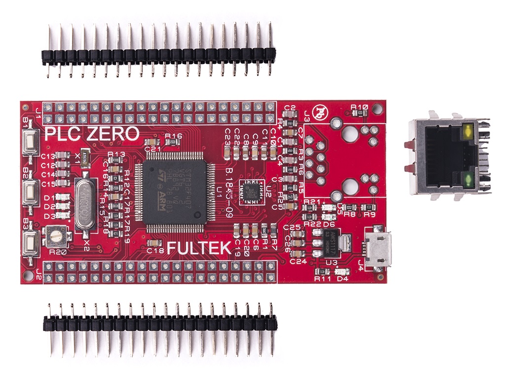
| CPU ZERO | SC-03210-00-00 | PLC development board. All pins are 3.3 v. and unprotected. You can use by learning PLC programming or automation project with IO shield board(you must make the IO shield yourself). Power 3.3 – 5 v. from usb. Total 42 IO on board. 3 button I 0.0 – I 0.2, 3 led Q 0.0 – Q 0.2, 1 Trimpot AI 0 on board. This product has no warranty and no discounts.Features: 115 KB program memory, 1 piece 10/100 MBit full duplex Ethernet, Modbus TCP, web server with 512KB file space, 2 piece RS485 serial port, Modbus RTU, 8 piece 200 KHz digital input and 8 piece 655 KHz digital output, 8 piece 12 Bit Analog input, 2 piece 12 Bit Analog output. 16 piece selectable digital inputs/outputs.Click for more information. | 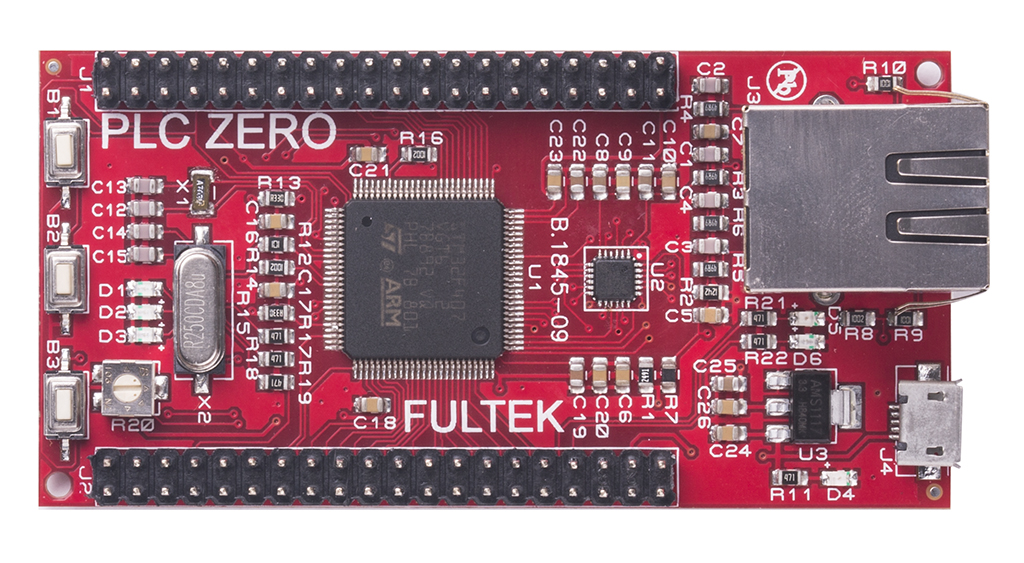 |
 |
30 |
| CPU STM32 | SC-03210-00-80 | It has the same features as PLC Zero. The only difference is that it has 2048 bytes of program memory. | |
|
15 |
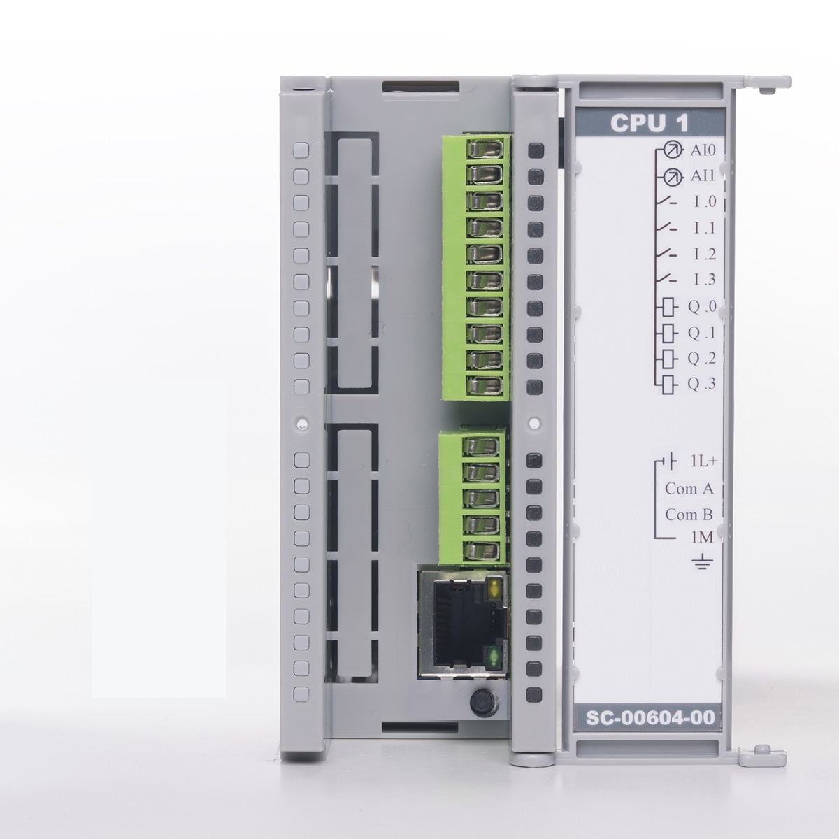
| CPU ONE | SC-00604-00-00 | 32 KB program memory, 1 piece 10/100 MBit full duplex Ethernet, Modbus TCP, web server with 512KB file space, 1 piece RS485 serial port, Modbus RTU, 4 piece 50 KHz digital input and 4 piece 40 KHz 0.5 Ampere digital output, 2 piece 0-10 V or 0-20 MA 12 Bit Analog input. Analog inputs can be used as digital input.You can download manual here and brochure here. | 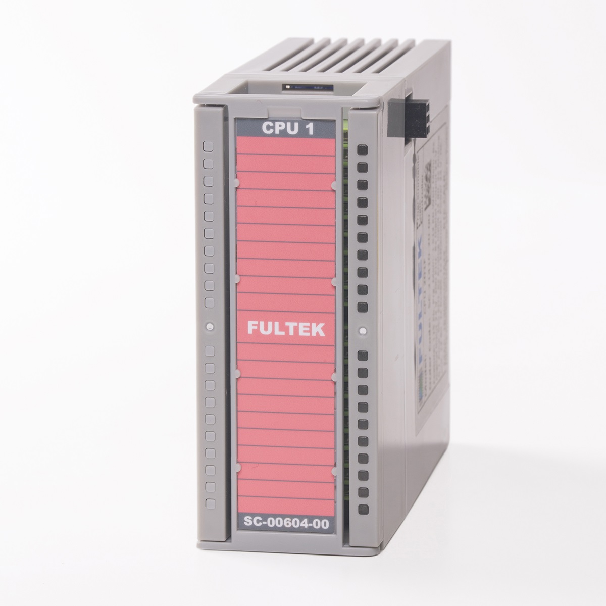 |
 |
90 |
| CPU 100 | SC-10808-00-00 | 32 KB program memory, 1 piece 10/100 MBit full duplex Ethernet, Modbus TCP, web server with 512KB file space, 1 piece RS485 serial port, Modbus RTU, 8 piece 50 KHz digital input and 8 piece 20 KHz 0.5 Ampere digital output.You can download manual here. |  |
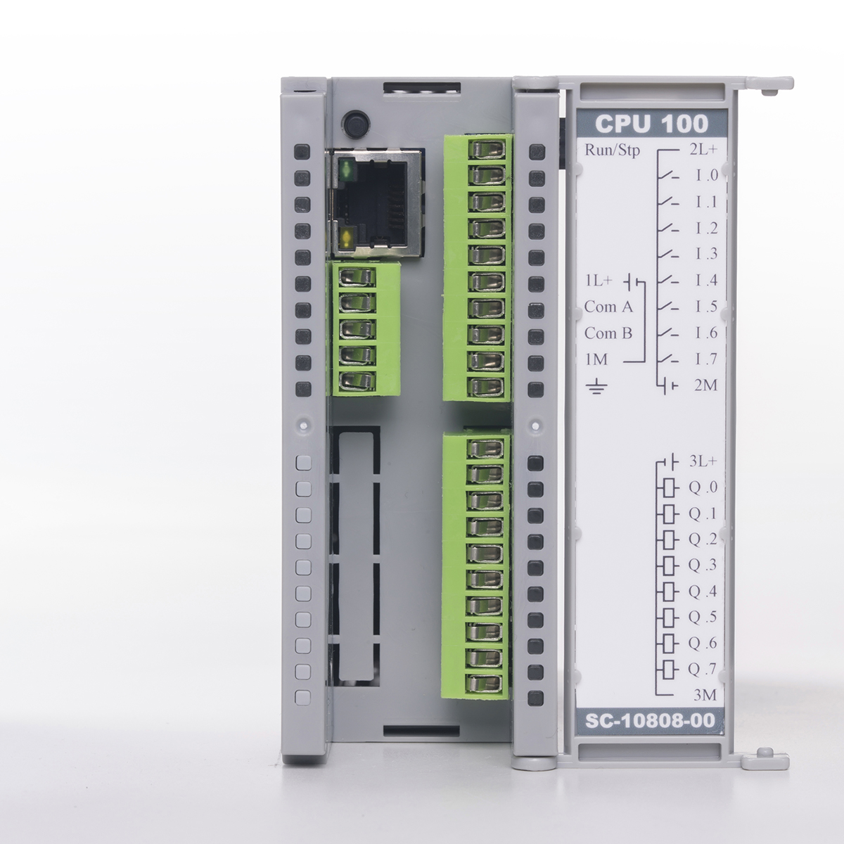 |
100 |
| CPU 100R | SC-10808-40-00 | 32 KB program memory, 1 piece 10/100 MBit full duplex Ethernet, Modbus TCP, web server with 512KB file space, 1 piece RS485 serial port, Modbus RTU, 8 piece 50 KHz digital input and 8 piece 2.00 Ampere relay output.You can download manual here. | 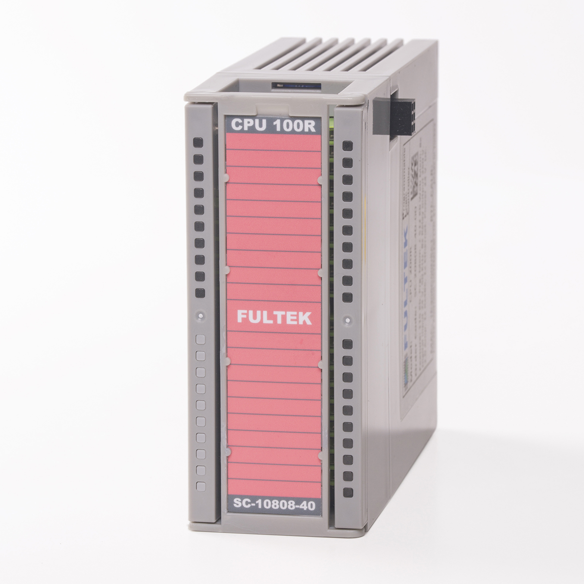 |
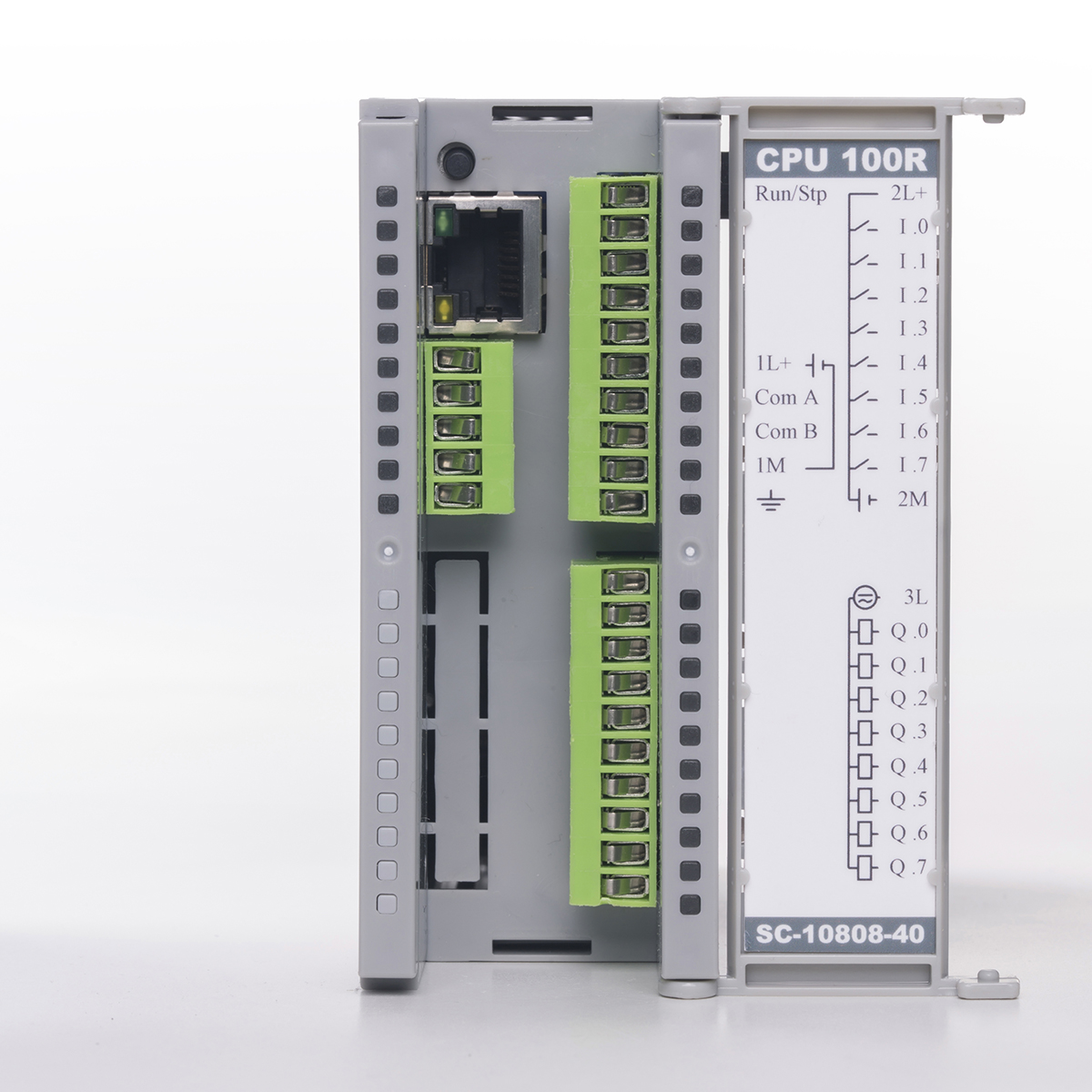 |
110 |
| CPU 100F | SC-10808-20-00 | 32 KB program memory, 1 piece 10/100 MBit full duplex Ethernet, Modbus TCP, web server with 512KB file space, 1 piece RS485 serial port, Modbus RTU, 8 piece 200 KHz digital input and 8 piece 655 KHz 0.1 Ampere digital output.You can download manual here. |  |
 |
150 |
| CPU 101 | SC-11410-00-00 | 32 KB program memory, 1 piece 10/100 MBit full duplex Ethernet, Modbus TCP, web server with 512KB file space, 1 piece RS485 serial port, Modbus RTU, 8 piece 50 KHz digital input and 8 piece 20 KHz 0.5 Ampere digital output, 6 piece 0-10 V or 0-20 MA 12 Bit Analog input, 1 piece 0-10 V and 1 piece 0-20 MA 12 Bit Analog output.You can download manual here. |  |
 |
150 |
| CPU 101R | SC-11410-40-00 | 32 KB program memory, 1 piece 10/100 MBit full duplex Ethernet, Modbus TCP, web server with 512KB file space, 1 piece RS485 serial port, Modbus RTU, 8 piece 50 KHz digital input and 8 piece 2.00 Ampere relay output, 6 piece 0-10 V or 0-20 MA 12 Bit Analog input, 1 piece 0-10 V and 1 piece 0-20 MA 12 Bit Analog output.You can download manual here. |  |
 |
160 |
| CPU 101F | SC-11410-20-00 | 32 KB program memory, 1 piece 10/100 MBit full duplex Ethernet, Modbus TCP, web server with 512KB file space, 1 piece RS485 serial port, Modbus RTU, 8 piece 200 KHz digital input and 8 piece 655 KHz 0.1 Ampere digital output, 6 piece 0-10 V or 0-20 MA 12 Bit Analog input, 1 piece 0-10 V and 1 piece 0-20 MA 12 Bit Analog output.You can download manual here. | 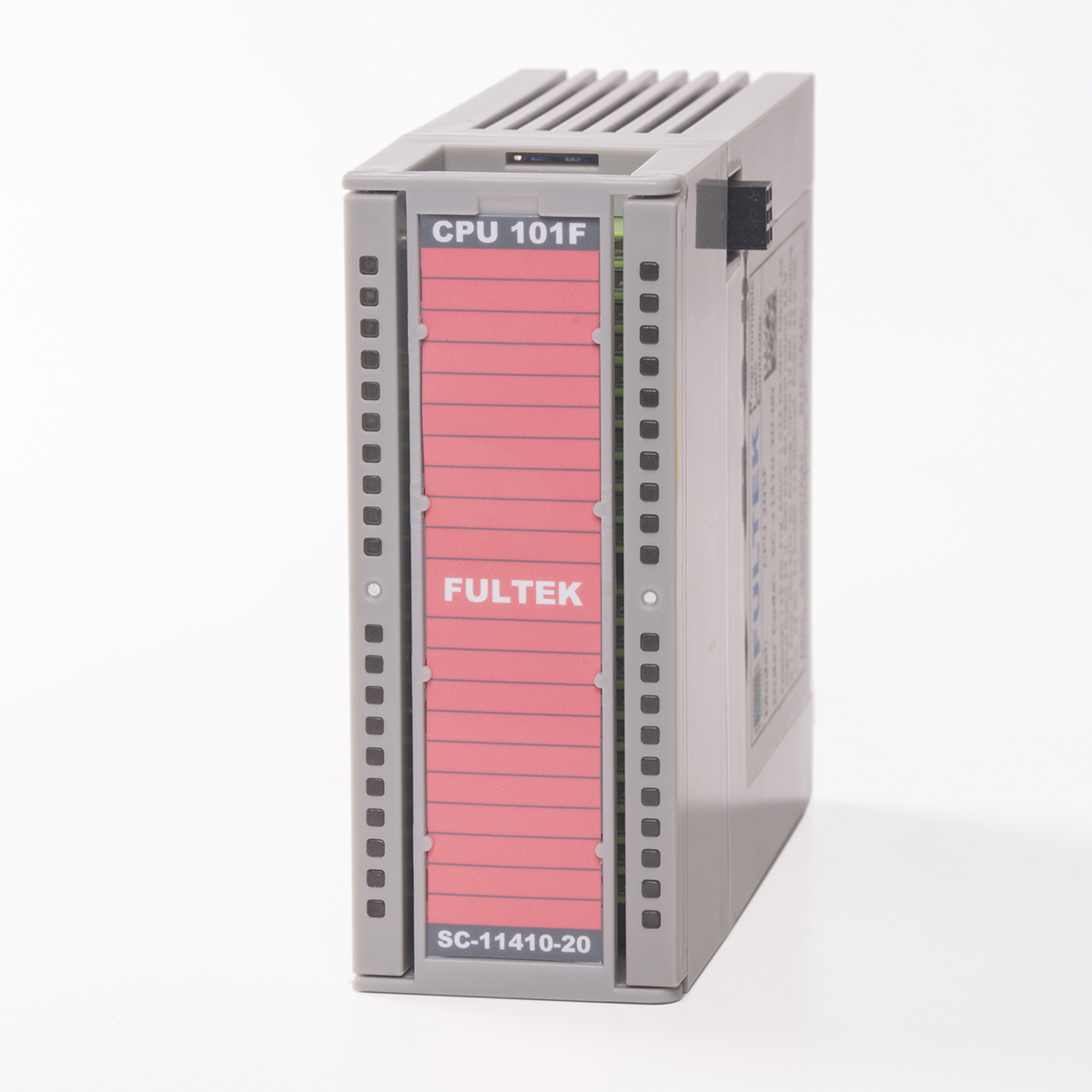 |
 |
200 |
| CPU 102 | SC-11210-00-00 | 32 KB program memory, 1 piece 10/100 MBit full duplex Ethernet, Modbus TCP, web server with 512KB file space, 2 piece RS485 serial port, Modbus RTU, 8 piece 50 KHz digital input and 8 piece 20 KHz 0.5 Ampere digital output, 4 piece 0-10 V or 0-20 MA 12 Bit Analog input, 1 piece 0-10 V and 1 piece 0-20 MA 12 Bit Analog output.You can download manual here. |  |
 |
175 |
| CPU 102R | SC-11210-40-00 | 32 KB program memory, 1 piece 10/100 MBit full duplex Ethernet, Modbus TCP, web server with 512KB file space, 2 piece RS485 serial port, Modbus RTU, 8 piece 50 KHz digital input and 8 piece 2.00 Ampere relay output, 4 piece 0-10 V or 0-20 MA 12 Bit Analog input, 1 piece 0-10 V and 1 piece 0-20 MA 12 Bit Analog output.You can download manual here. |  |
 |
185 |
| CPU 102F | SC-11210-20-00 | 32 KB program memory, 1 piece 10/100 MBit full duplex Ethernet, Modbus TCP, web server with 512KB file space, 2 piece RS485 serial port, Modbus RTU, 8 piece 200 KHz digital input and 8 piece 655 KHz 0.1 Ampere digital output, 4 piece 0-10 V or 0-20 MA 12 Bit Analog input, 1 piece 0-10 V and 1 piece 0-20 MA 12 Bit Analog output.You can download manual here. |  |
 |
225 |
| CPU 200 | SC-20808-00-00 | 115 KB program memory, 1 piece 10/100 MBit full duplex Ethernet, Modbus TCP, web server with 512KB file space, 1 piece RS485 serial port, Modbus RTU, 8 piece 50 KHz digital input and 8 piece 20 KHz 0.5 Ampere digital output.You can download manual here. | 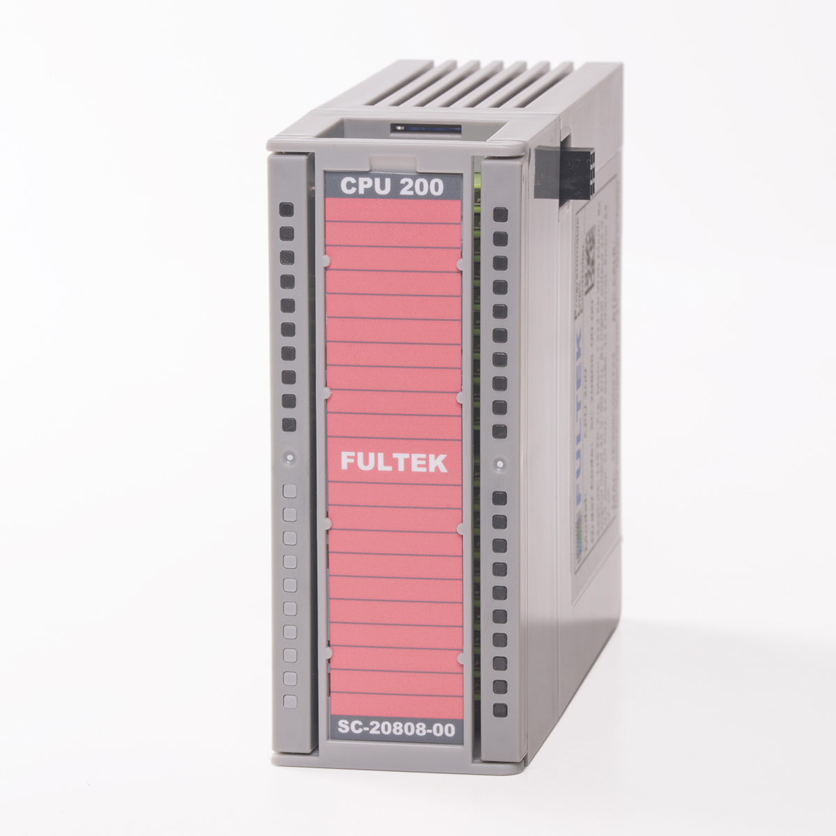 |
 |
200 |
| CPU 200R | SC-20808-40-00 | 115 KB program memory, 1 piece 10/100 MBit full duplex Ethernet, Modbus TCP, web server with 512KB file space, 1 piece RS485 serial port, Modbus RTU, 8 piece 50 KHz digital input and 8 piece 2.00 Ampere relay output.You can download manual here. |  |
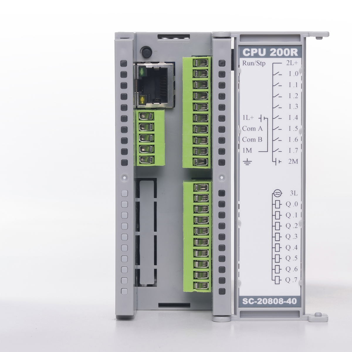 |
210 |
| CPU 200F | SC-20808-20-00 | 115 KB program memory, 1 piece 10/100 MBit full duplex Ethernet, Modbus TCP, web server with 512KB file space, 1 piece RS485 serial port, Modbus RTU, 8 piece 200 KHz digital input and 8 piece 655 KHz 0.1 Ampere digital output.You can download manual here. | 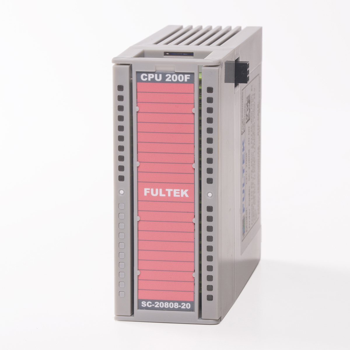 |
 |
250 |
| CPU 201 | SC-21410-00-00 | 115 KB program memory, 1 piece 10/100 MBit full duplex Ethernet, Modbus TCP, web server with 512KB file space, 1 piece RS485 serial port, Modbus RTU, 8 piece 50 KHz digital input and 8 piece 20 KHz 0.5 Ampere digital output, 6 piece 0-10 V or 0-20 MA 12 Bit Analog input, 1 piece 0-10 V and 1 piece 0-20 MA 12 Bit Analog output.You can download manual here. |  |
 |
250 |
| CPU 201R | SC-21410-40-00 | 115 KB program memory, 1 piece 10/100 MBit full duplex Ethernet, Modbus TCP, web server with 512KB file space, 1 piece RS485 serial port, Modbus RTU, 8 piece 50 KHz digital input and 8 piece 2.00 Ampere relay output, 6 piece 0-10 V or 0-20 MA 12 Bit Analog input, 1 piece 0-10 V and 1 piece 0-20 MA 12 Bit Analog output.You can download manual here. | |
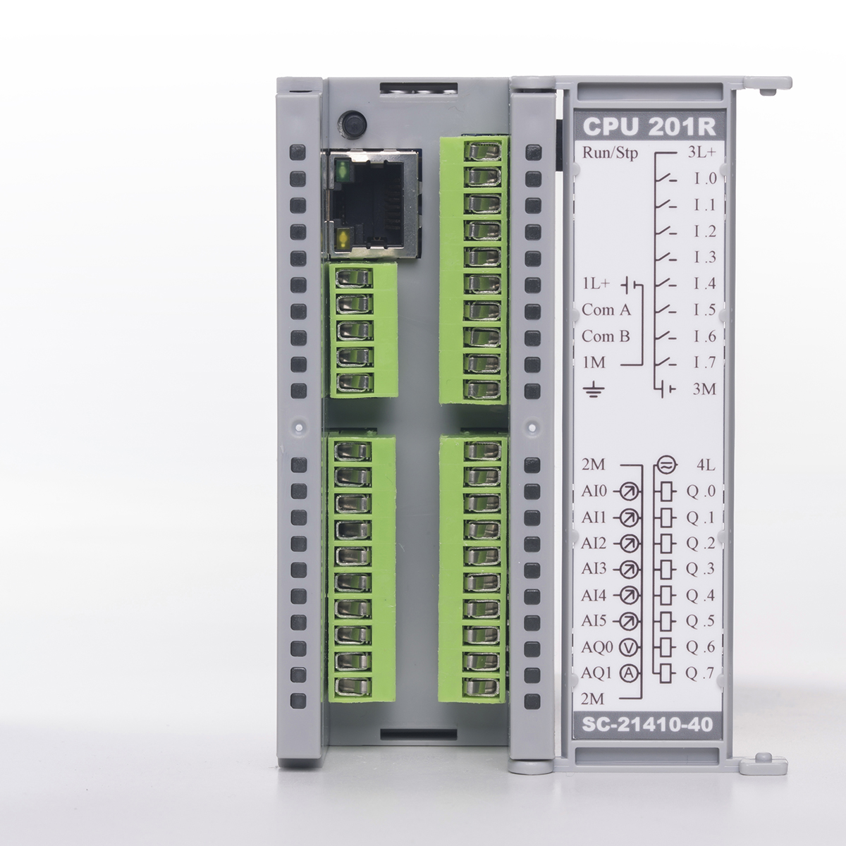 |
260 |
| CPU 201F | SC-21410-20-00 | 115 KB program memory, 1 piece 10/100 MBit full duplex Ethernet, Modbus TCP, web server with 512KB file space, 1 piece RS485 serial port, Modbus RTU, 8 piece 200 KHz digital input and 8 piece 655 KHz 0.1 Ampere digital output, 6 piece 0-10 V or 0-20 MA 12 Bit Analog input, 1 piece 0-10 V and 1 piece 0-20 MA 12 Bit Analog output.You can download manual here. |  |
 |
300 |
| CPU 202 | SC-21210-00-00 | 115 KB program memory, 1 piece 10/100 MBit full duplex Ethernet, Modbus TCP, web server with 512KB file space, 2 piece RS485 serial port, Modbus RTU, 8 piece 50 KHz digital input and 8 piece 20 KHz 0.5 Ampere digital output, 4 piece 0-10 V or 0-20 MA 12 Bit Analog input, 1 piece 0-10 V and 1 piece 0-20 MA 12 Bit Analog output.You can download manual here. | 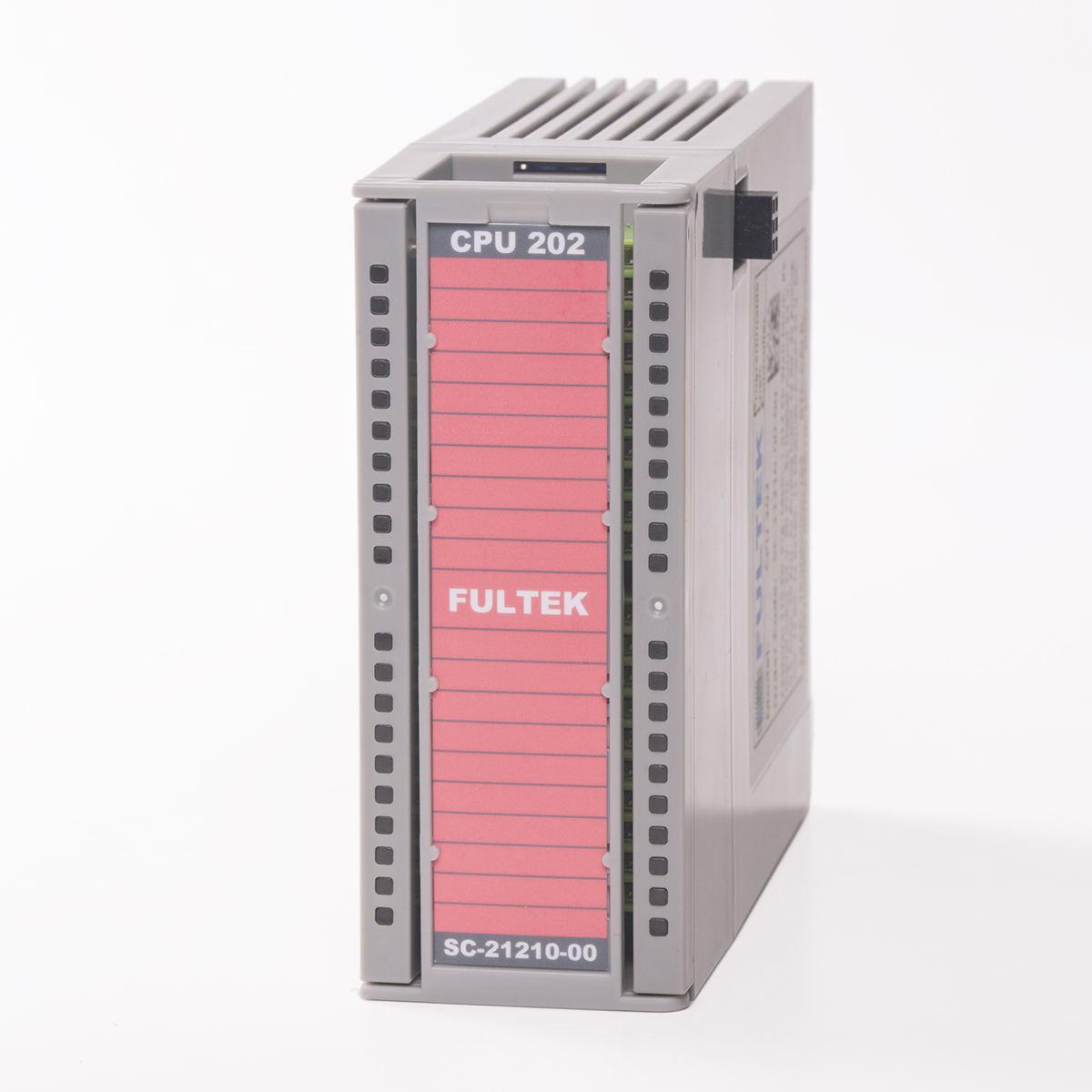 |
 |
275 |
| CPU 202R | SC-21210-40-00 | 115 KB program memory, 1 piece 10/100 MBit full duplex Ethernet, Modbus TCP, web server with 512KB file space, 2 piece RS485 serial port, Modbus RTU, 8 piece 50 KHz digital input and 8 piece 2.00 Ampere relay output, 4 piece 0-10 V or 0-20 MA 12 Bit Analog input, 1 piece 0-10 V and 1 piece 0-20 MA 12 Bit Analog output.You can download manual here. |  |
 |
285 |
| CPU 202F | SC-21210-20-00 | 115 KB program memory, 1 piece 10/100 MBit full duplex Ethernet, Modbus TCP, web server with 512KB file space, 2 piece RS485 serial port, Modbus RTU, 8 piece 200 KHz digital input and 8 piece 655 KHz 0.1 Ampere digital output, 4 piece 0-10 V or 0-20 MA 12 Bit Analog input, 1 piece 0-10 V and 1 piece 0-20 MA 12 Bit Analog output.You can download manual here. | 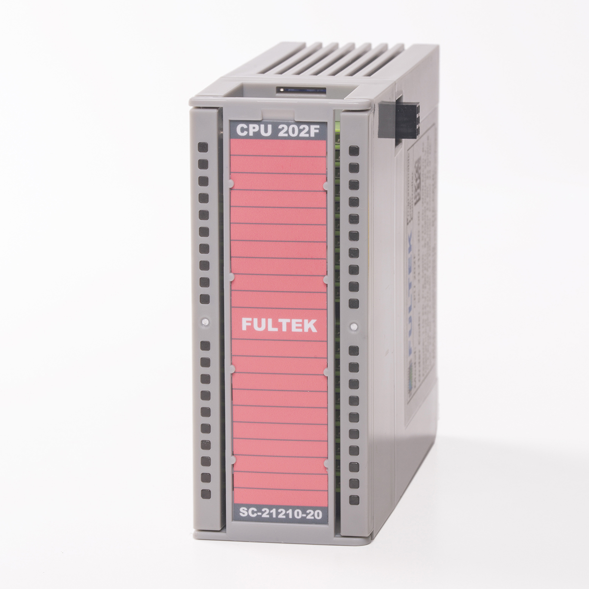 |
 |
325 |
| CPU 301 | SC-31410-00-00 | 175 KB program memory, 4 GB SD Card for data logging, 1 piece 10/100 MBit full duplex Ethernet, Modbus TCP, web server with 512KB file space, 1 piece RS485 serial port, Modbus RTU, 8 piece 50 KHz digital input and 8 piece 20 KHz 0.5 Ampere digital output, 6 piece 0-10 V or 0-20 MA 12 Bit Analog input, 1 piece 0-10 V and 1 piece 0-20 MA 12 Bit Analog output.You can download manual here. | |
|
500 |
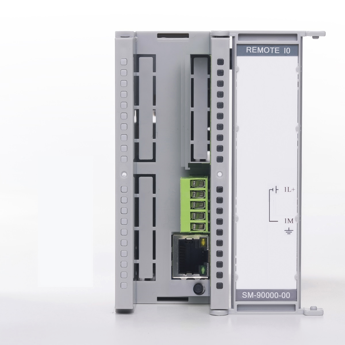
| REMOTE CPU | SM-90000-00-00 | Can be add 32 REMOTE IO CPU modules on the Fulmatic 7 PLCs. Each REMOTE IO CPU module can be equipped four rack. Can be add 16 modules for each rack. Total 60 IO module can be equipped for each REMOTE IO CPU. The main CPU reads and writes input / output values from all REMOTE IO CPU modules simultaneously with the Ethernet UDP protocol. CP modules cannot be added to REMOTE IO CPU modules.You can download manual here. | 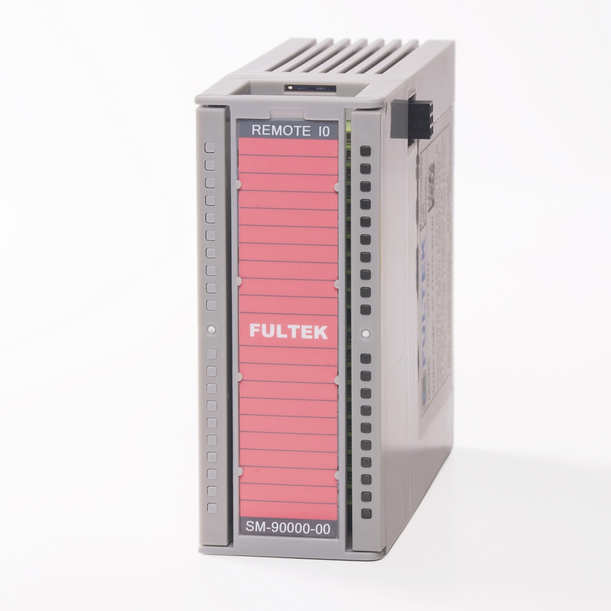 |
 |
100 |
PLC Extension Module
| Ad | Sipariş Kodu | Açıklama | Resim | Resim | Fiyat (USD) |
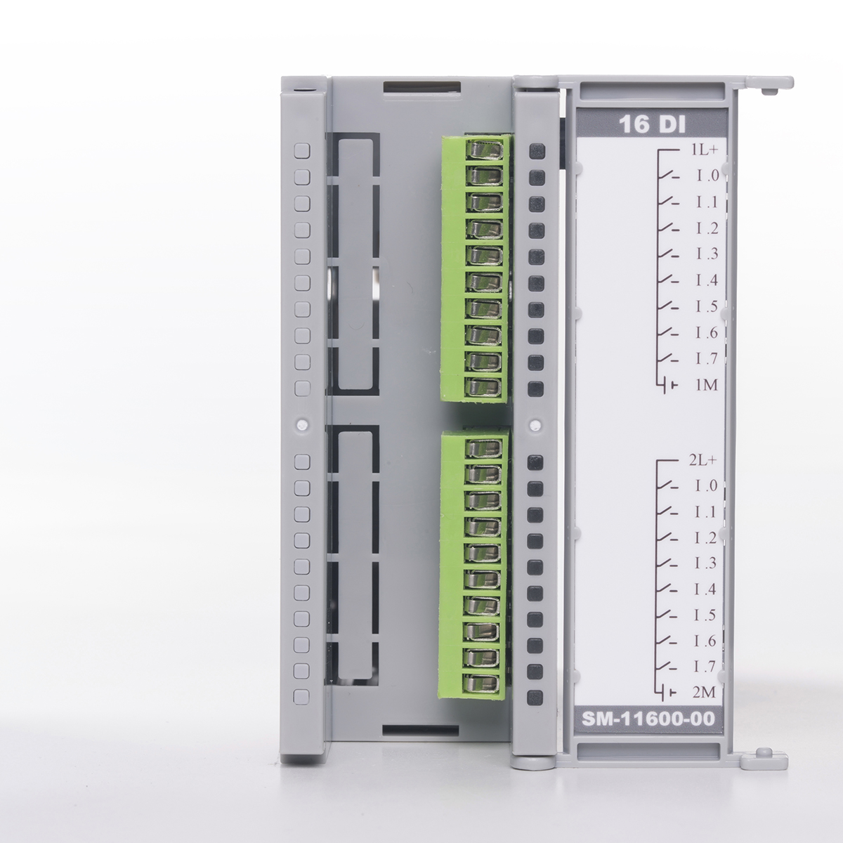
| 16 DI | SM-11600-00-00 | 16 channel optical isolated digital input module. Supply voltage 20-28 V. DC. The maximum frequency is 50 Khz. | 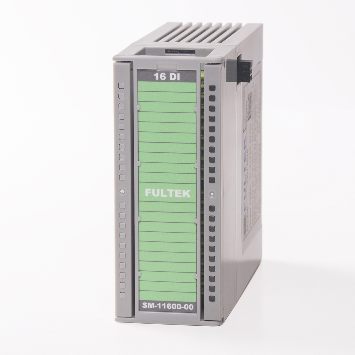 |
 |
60 |
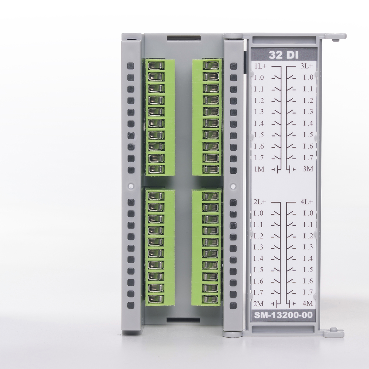
| 32 DI | SM-13200-00-00 | 32 channel optical isolated digital input module. Supply voltage 20-28 V. DC. The maximum frequency is 50 Khz. | 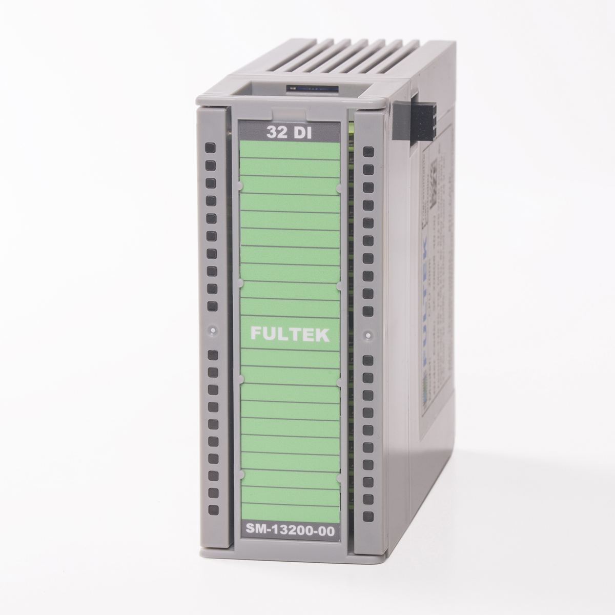 |
 |
100 |
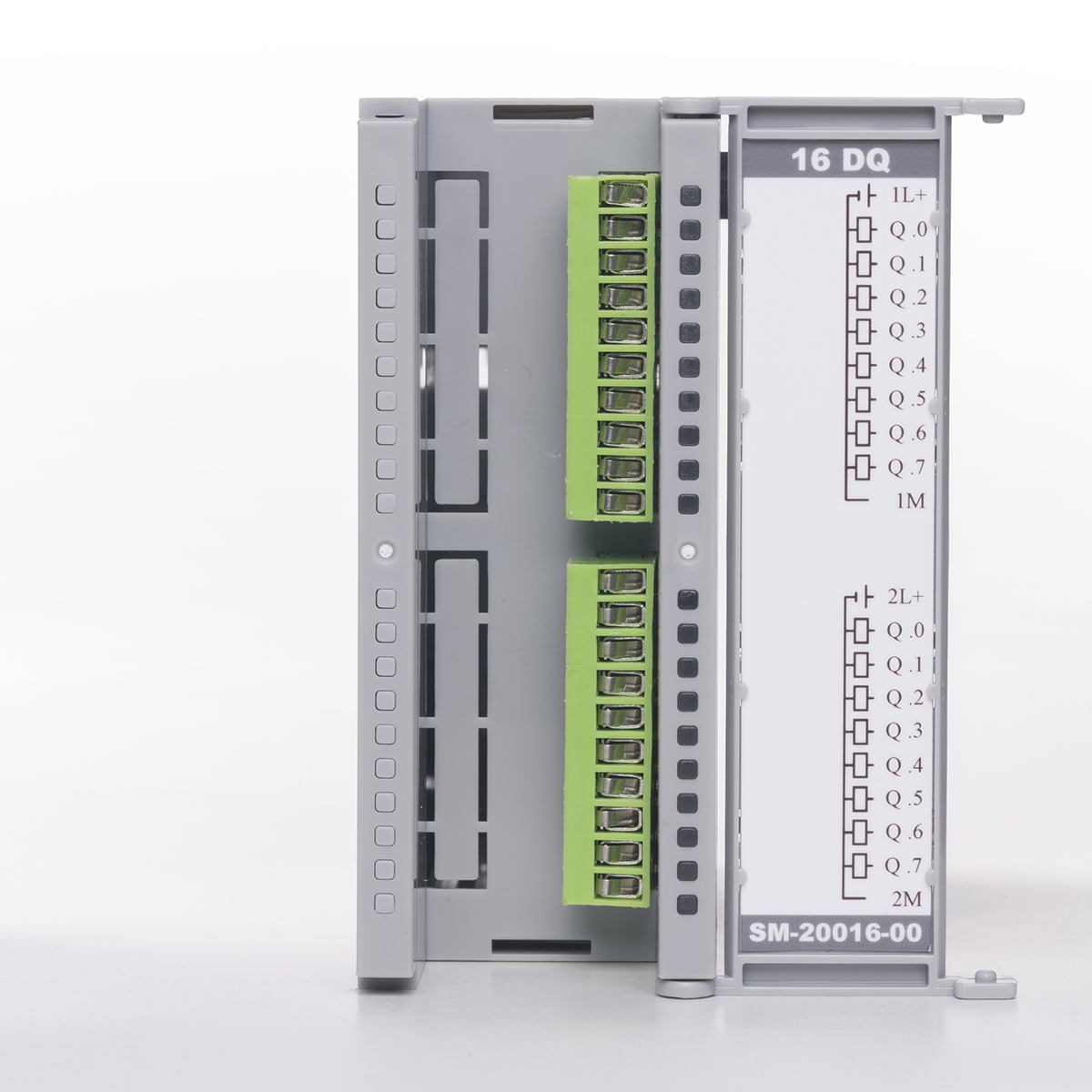
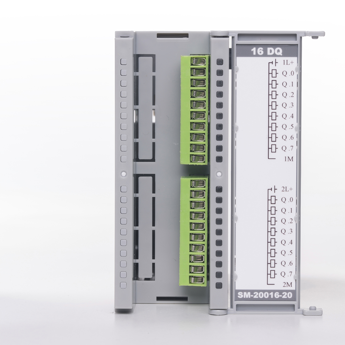
| 16 DQ | SM-20016-00-00 | 16 channel optical isolated digital output module. Supply voltage 20-28 V. DC. Output current 0.5 Amp. Maximum frequency 40 Khz. | 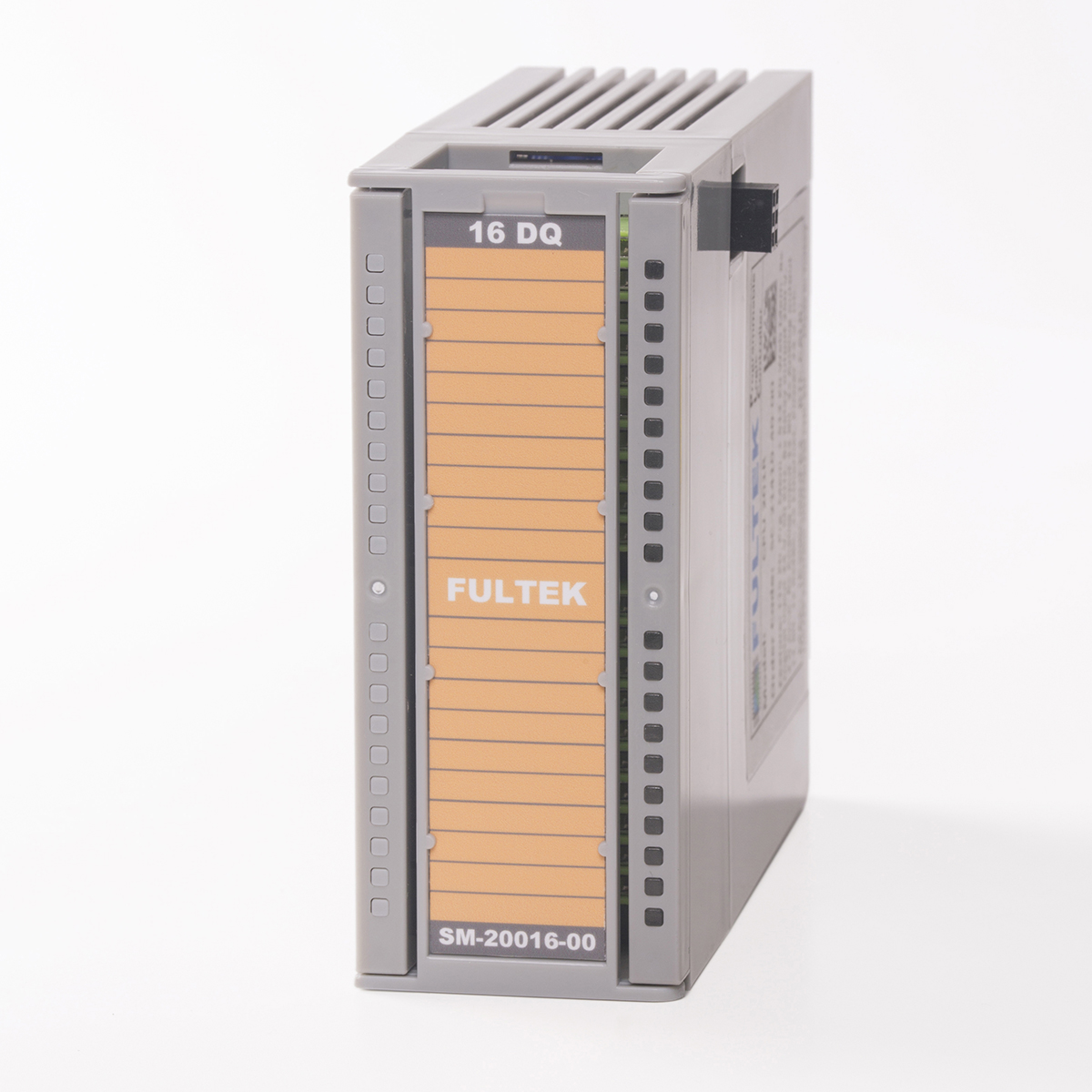 |
 |
80 |
| 16 DQ 2A. | SM-20016-20-00 | 16 channel optical isolated digital output module. Supply voltage 20-28 V. DC. Output current 2.0 Amp. Maximum frequency 30 Khz. | 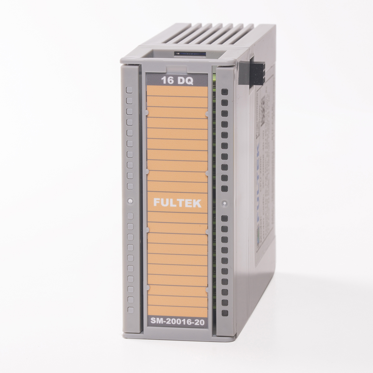 |
 |
100 |
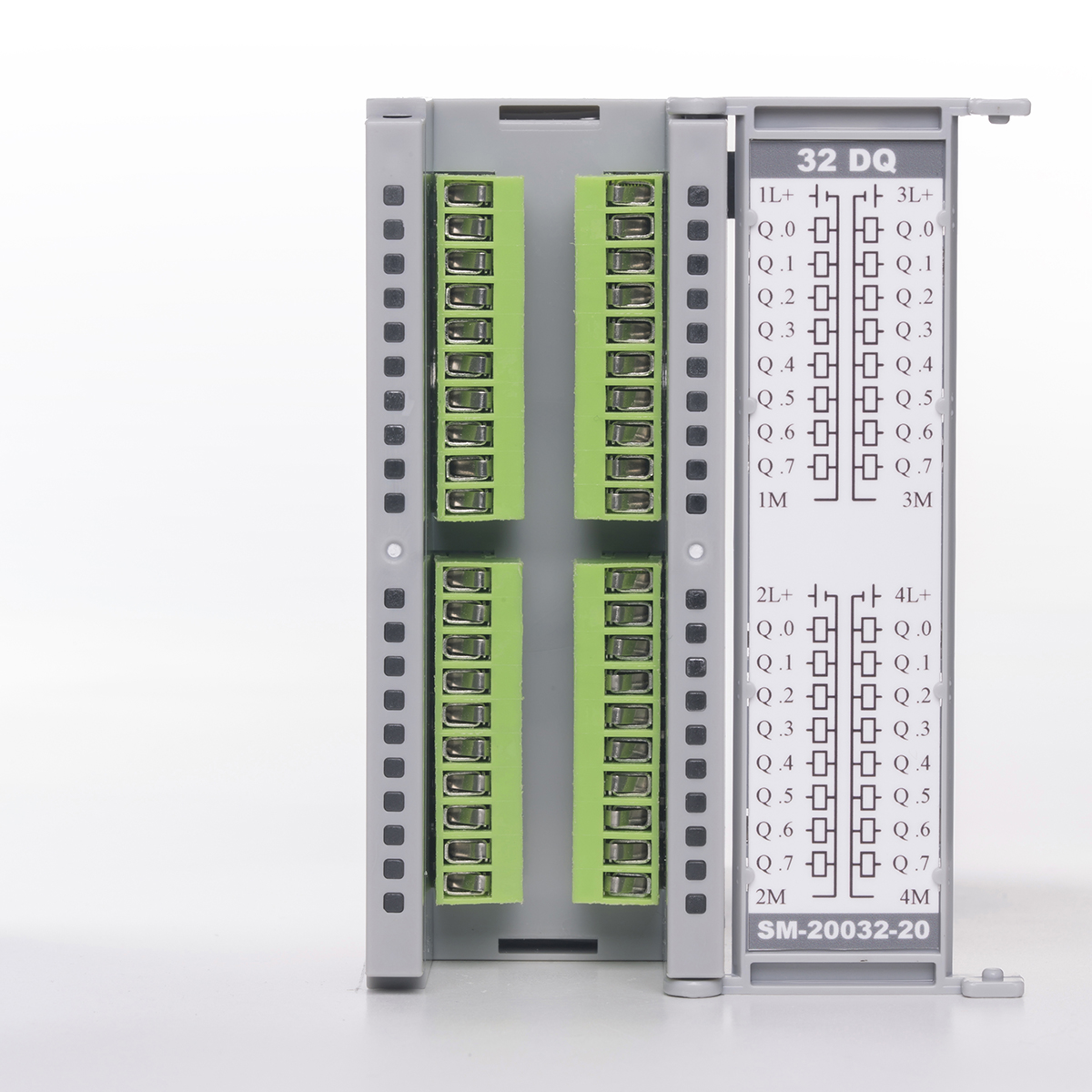
| 32 DQ | SM-20032-00-00 | 32 channel optical isolated digital output module. Supply voltage 20-28 V. DC. Output current 0.5 Amp. Maximum frequency 40 Khz. |  |
 |
135 |
| 32 DQ 2A. | SM-20032-20-00 | 32 channel optical isolated digital output module. Supply voltage 20-28 V. DC. Output current 2.0 Amp. Maximum frequency 30 Khz. |  |
 |
165 |
| 8 RQ MC. | SM-20008-50-00 | 8 Channel relay output module. Supply voltage 20-28 V. DC. Contacts 250 V. 2.0 Amp. All contacts are free terminal. |  |
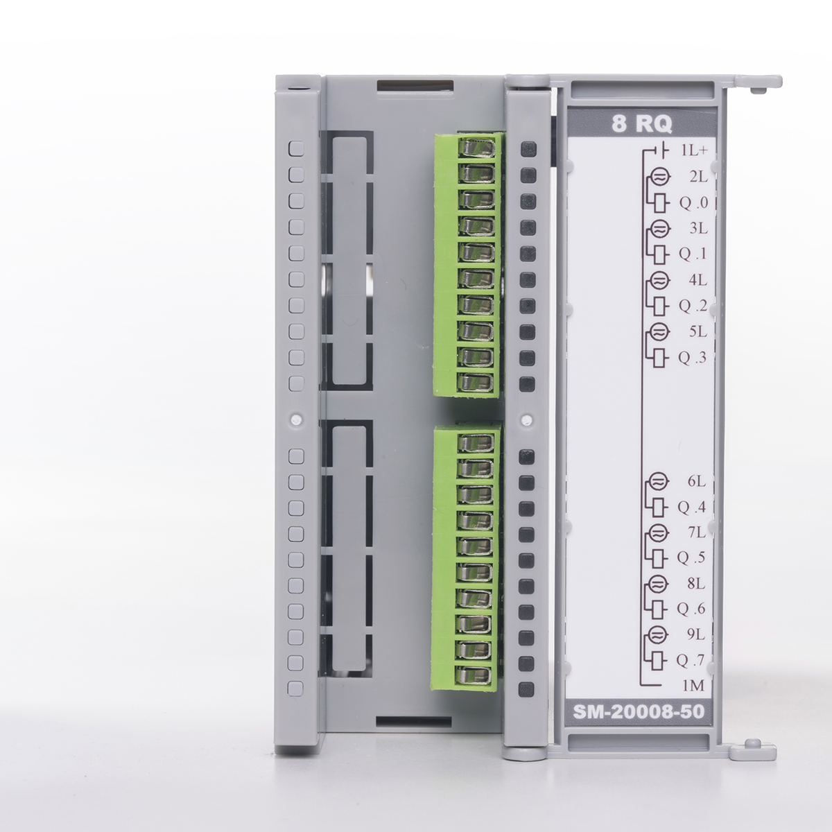 |
60 |
| 16 RQ MC. | SM-20016-50-00 | 16 Channel relay output module. Supply voltage 20-28 V. DC. Contacts 250 V. 2.0 Amp. All contacts are free terminal. | 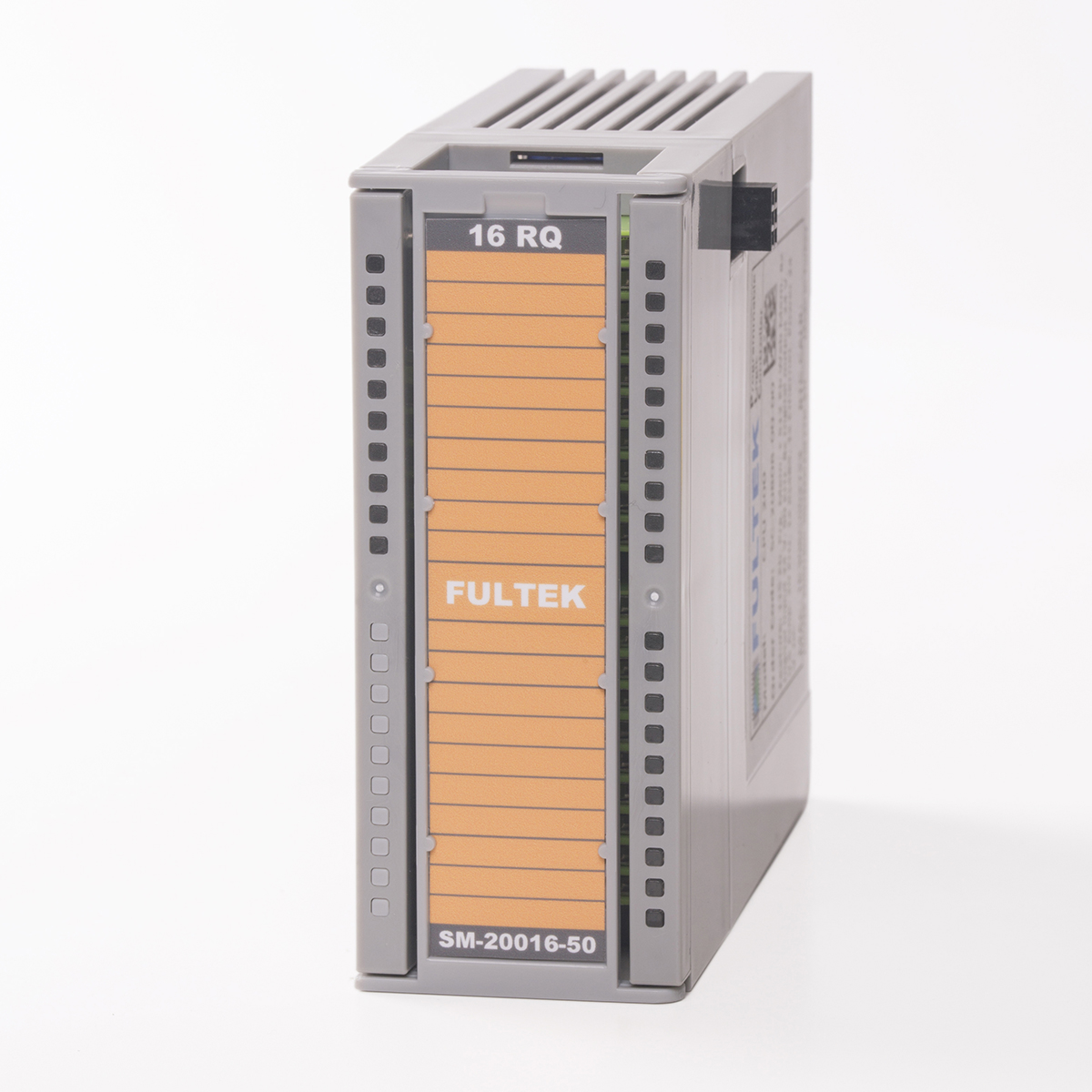 |
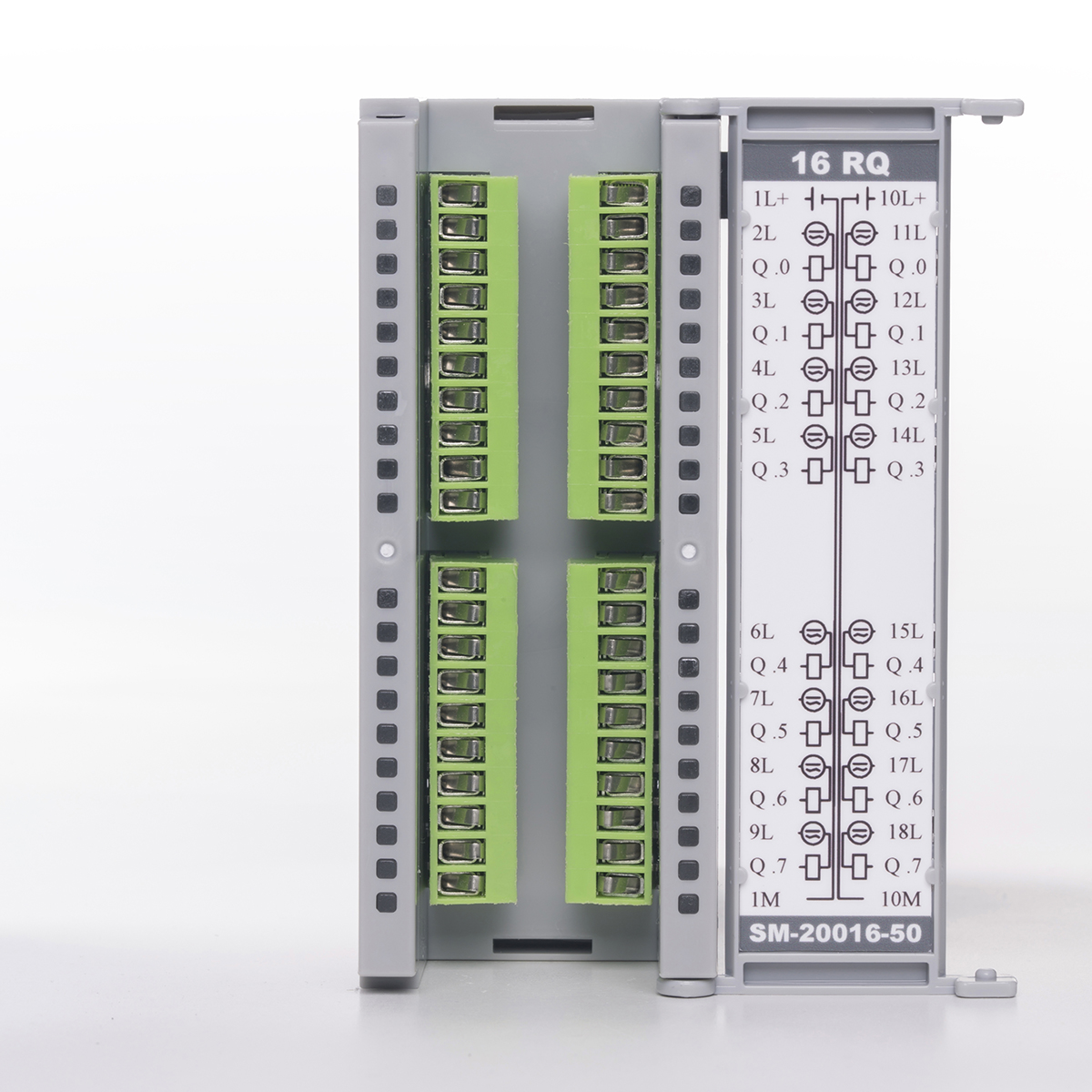 |
100 |
| 16 RQ SC. | SM-20016-40-00 | 16 Channel relay output module. Supply voltage 20-28 V. DC. Contacts 250 V. 2.0 Amp. The maximum current is 10 amps per terminal group. |  |
 |
90 |
| 32 RQ SC. | SM-20032-40-00 | 32 Channel relay output module. Supply voltage 20-28 V. DC. Contacts 250 V. 2.0 Amp. The maximum current is 10 amps per terminal group. | 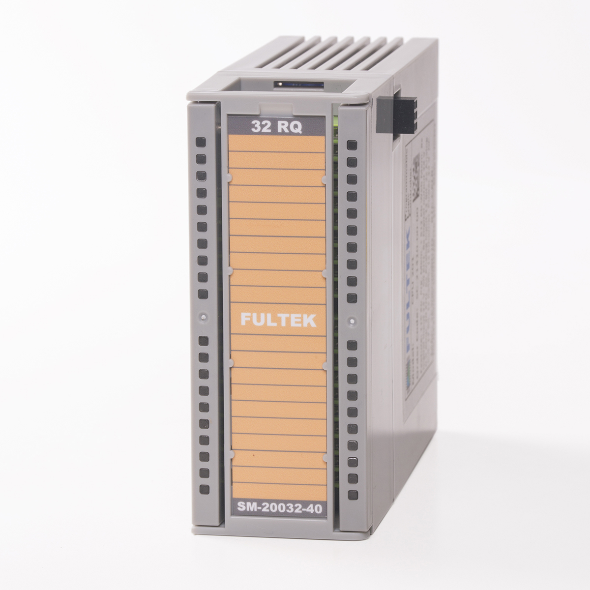 |
 |
150 |
| 8DI / 8DQ | SM-30808-00-00 | 8 channel optical isolated digital input and 8 channel optical isolated digital output module. Supply voltage 20-28 V. DC. Digital output current 0.5 Amp. Maximum input frequency 50 Khz, output frequency 40 Khz. |  |
 |
70 |
| 8DI / 8DQ 2A. | SM-30808-20-00 | 8 channel optical isolated digital input and 8 channel optical isolated digital output module. Supply voltage 20-28 V. DC. Digital output current 2.0 Amp. 10 amp maximum current for output terminal group. The maximum input frequency is 50 kHz, the output frequency is 30 KHz. |  |
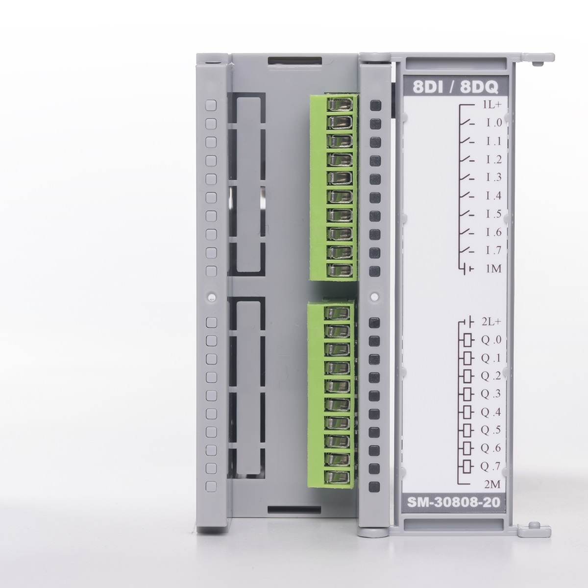 |
80 |
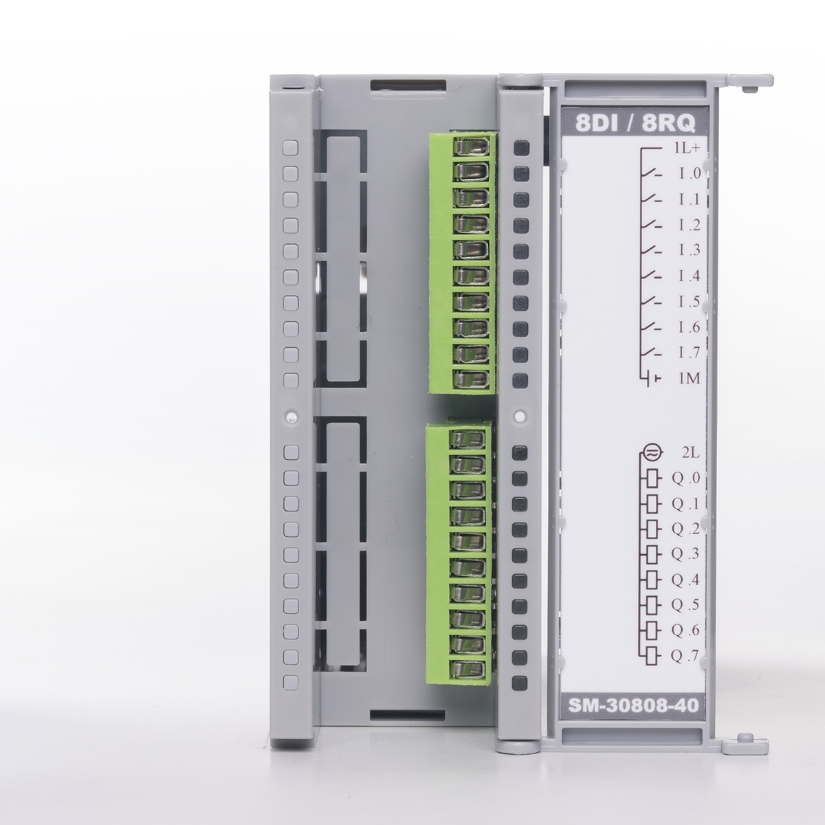
| 8DI / 8RQ | SM-30808-40-00 | 8 channel optical isolated digital input and 8 channel relay output module. Supply voltage 20-28 V. DC. Contacts 250 V 2.0 Amp. 10 amp for maximum current output terminal group. Maximum input frequency 50 KHz. | 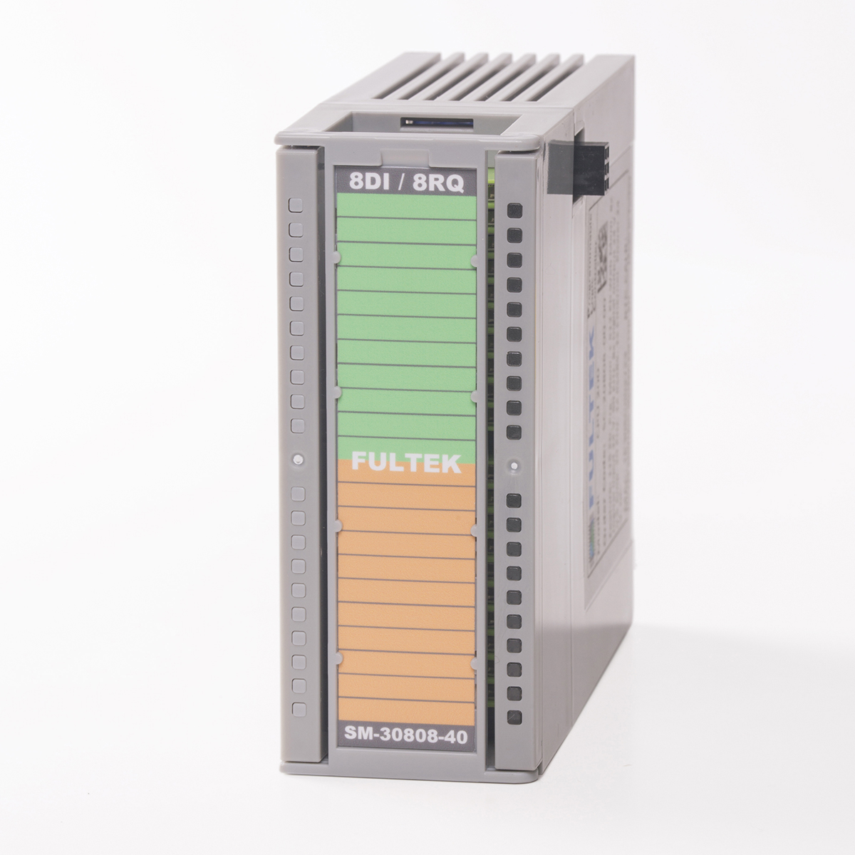 |
 |
75 |
| 16DI / 16DQ | SM-31616-00-00 | 16 channel optical isolated digital input and 16 channel optical isolated digital output module. Supply voltage 20-28 V. DC. Digital output current 0.5 Amp. Maximum input frequency 50 Khz, output frequency 40 Khz. |  |
 |
120 |
| 16DI / 16DQ 2A. | SM-31616-20-00 | 16 channel optical isolated digital input and 16 channel optical isolated digital output module. Supply voltage 20-28 V. DC. Digital output current 2.0 Amp. 10 amp maximum current for output terminal group. The maximum input frequency is 50 kHz, the output frequency is 30 KHz. |  |
 |
140 |
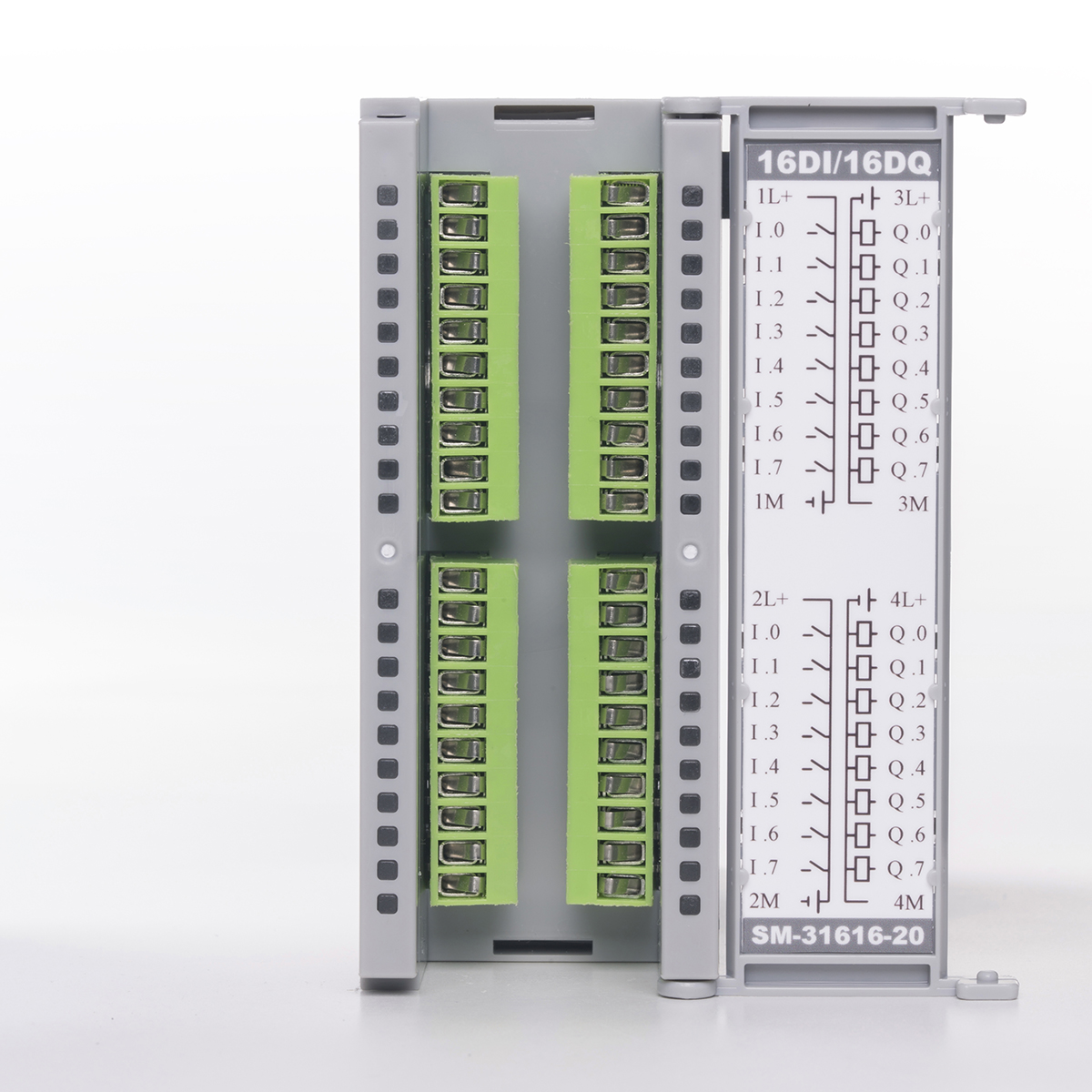
| 16DI / 16RQ | SM-31616-40-00 | 16 channel optical isolated digital input and 16 channel relay output module. Supply voltage 20-28 V. DC. Contacts 250 V 2.0 Amp. 10 amp for maximum current output terminal group. Maximum input frequency 50 KHz. |  |
 |
130 |
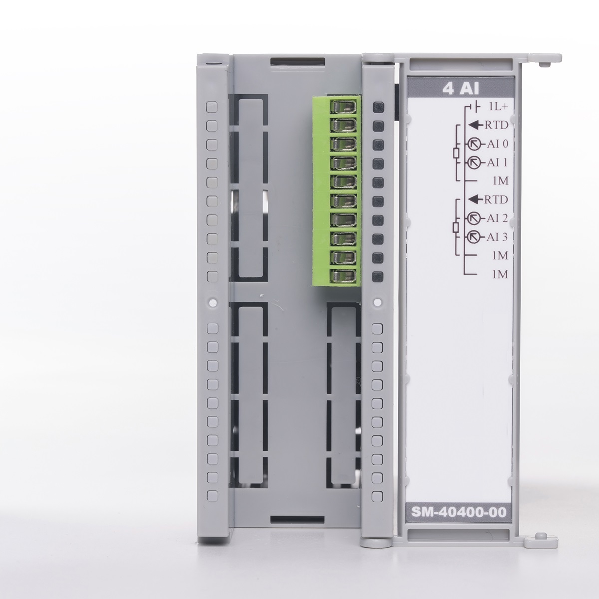
| 4 AI | SM-40400-00-00 | 4 Channel analog input module (2 channels when Pt100, PT1000 and Resistor). Signal types: 0-10 V. / 0-20 MA. / PT100 / PT1000 / Resistor / Thermocouple B, E, J, K, N, R, S, T. Resolution 16 bit. Minimum 1000 samples per second. | 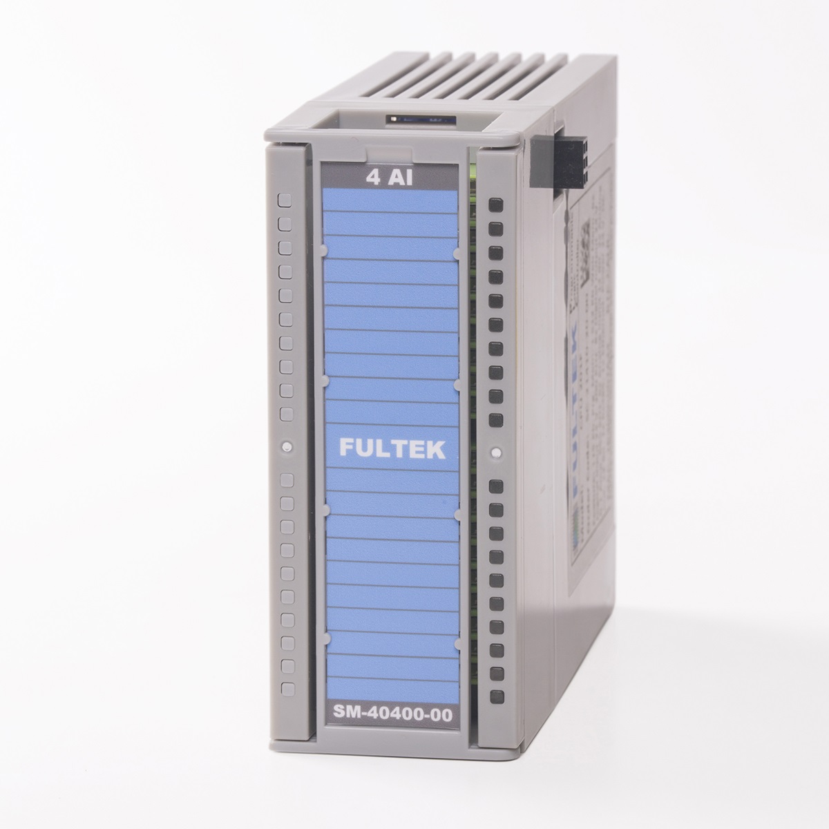 |
 |
100 |
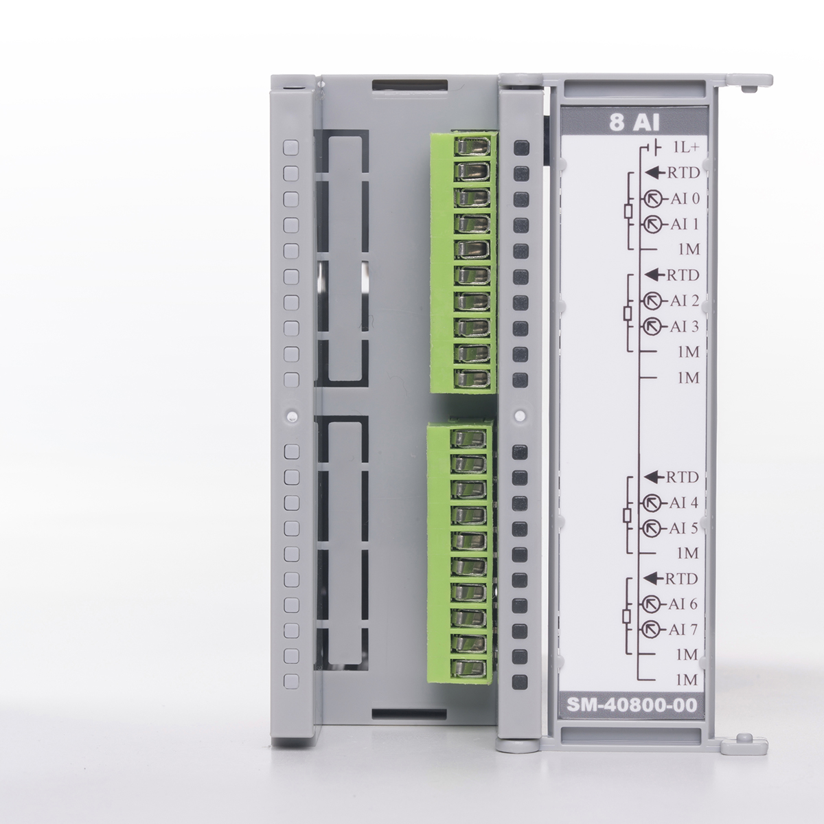
| 8 AI | SM-40800-00-00 | 8 Channel analog input module (4 channels when Pt100, PT1000 and Resistor). Signal types: 0-10 V. / 0-20 MA. / PT100 / PT1000 / Resistor / Thermocouple B, E, J, K, N, R, S, T. Resolution 16 bit. Minimum 500 samples per second. | 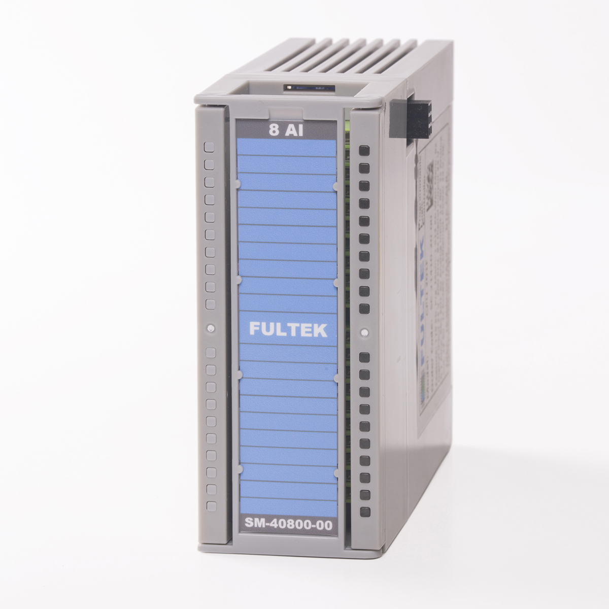 |
 |
150 |
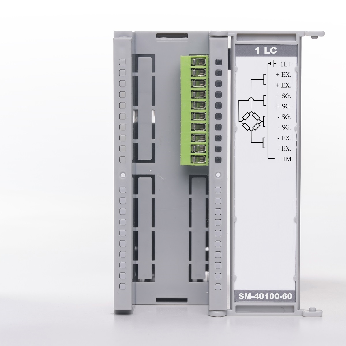
| 1 LC | SM-40100-60-00 | 1 Channel Loadcell input module. -19mv / + 19mv, resolution 20 bit. 80 samples per second. Maximum 16 Loadcells (350 ohm) can be connect | 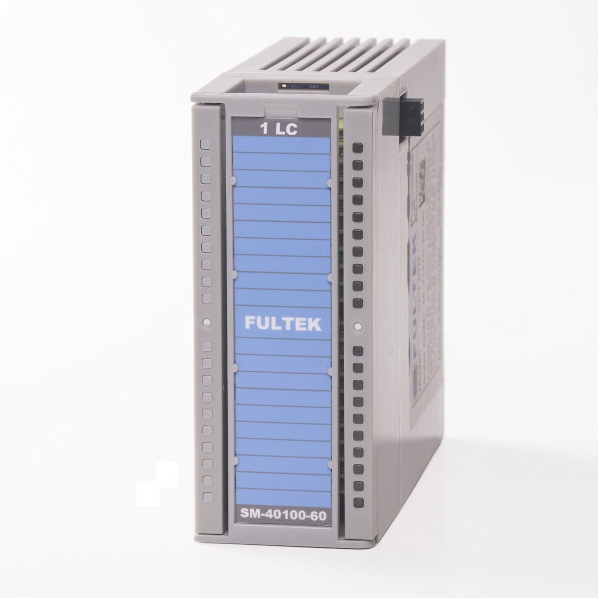 |
 |
100 |
| 2 LC | SM-40200-60-00 | 2 Channel Loadcell input module. -19mv / + 19mv, resolution 20 bit. 80 samples per second. Maximum 8 Loadcells (350 ohm) can be connect to each channel. |  |
 |
150 |
| 4 AQ 12B. | SM-50004-00-00 | 4 Channel 12 bit analog output module. Each channel have three outputs 0-5 V / 0-10 V / 0-20 Ma. All outputs can be used at the same time. The maximum current for voltage output channels is max. 20 Ma. 50000 samples per second. | 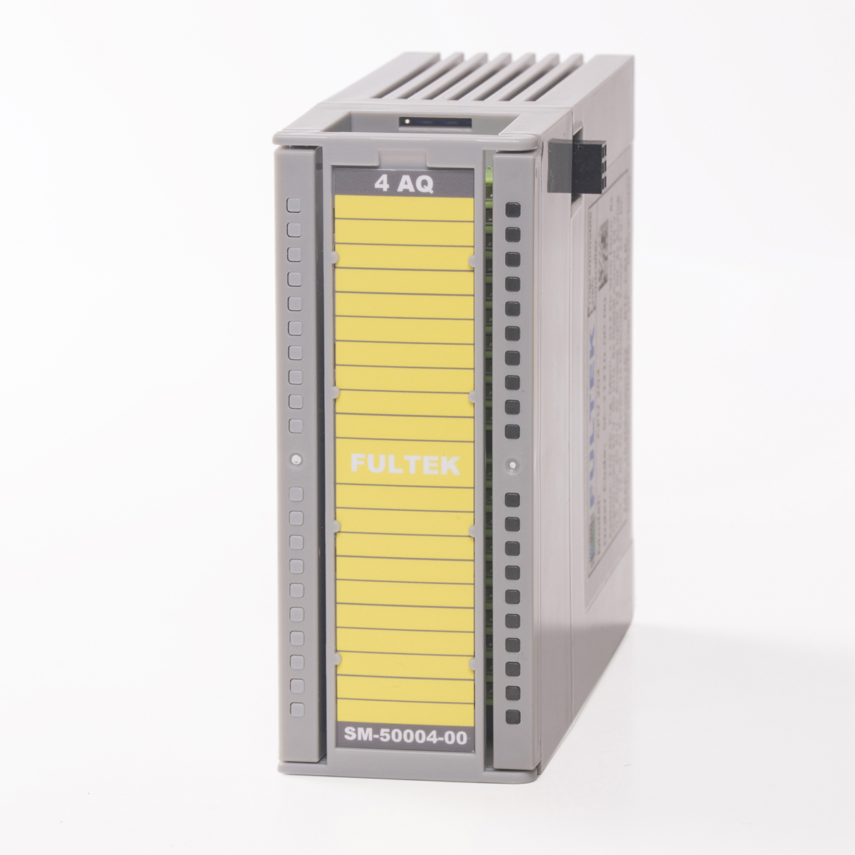 |
 |
110 |
| 4 AQ 16B. | SM-50004-20-00 | 4 Channel 16 bit analog output module. Each channel have three outputs 0-5 V / 0-10 V / 0-20 Ma. All outputs can be used at the same time. The maximum current for voltage output channels is max. 20 Ma. 50000 samples per second. |  |
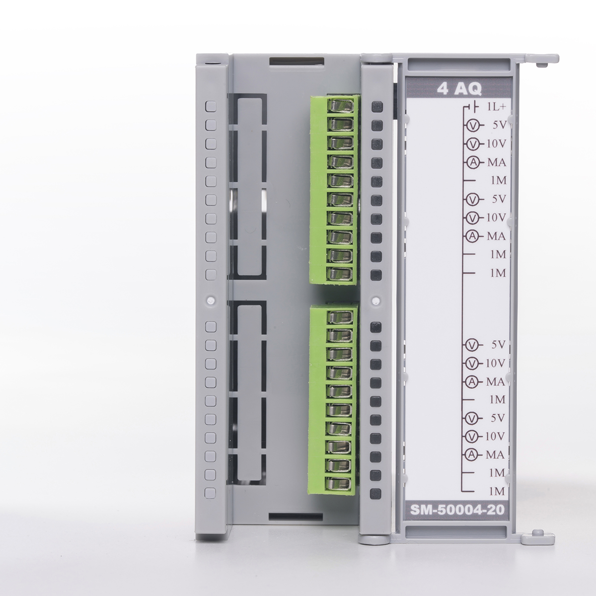 |
150 |
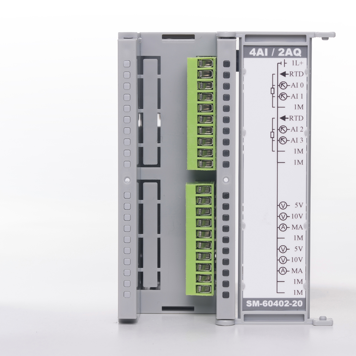
| 4AI / 2AQ 12B. | SM-60402-00-00 | 4 channel 16 bit analog input (2 channels when Pt100, PT1000 and Resistor) and 2 channels 12 bit analog output module. Analog input signal types: 0-10 V. / 0-20 MA. / PT100 / PT1000 / Resistor / Thermocouple B, E, J, K, N, R, S, T. Each analog output channel have three outputs 0-5 V / 0-10 V / 0-20 Ma. All outputs can be used at the same time. The maximum current for voltage output channels is max. 20 Ma. 1000 samples per second. |  |
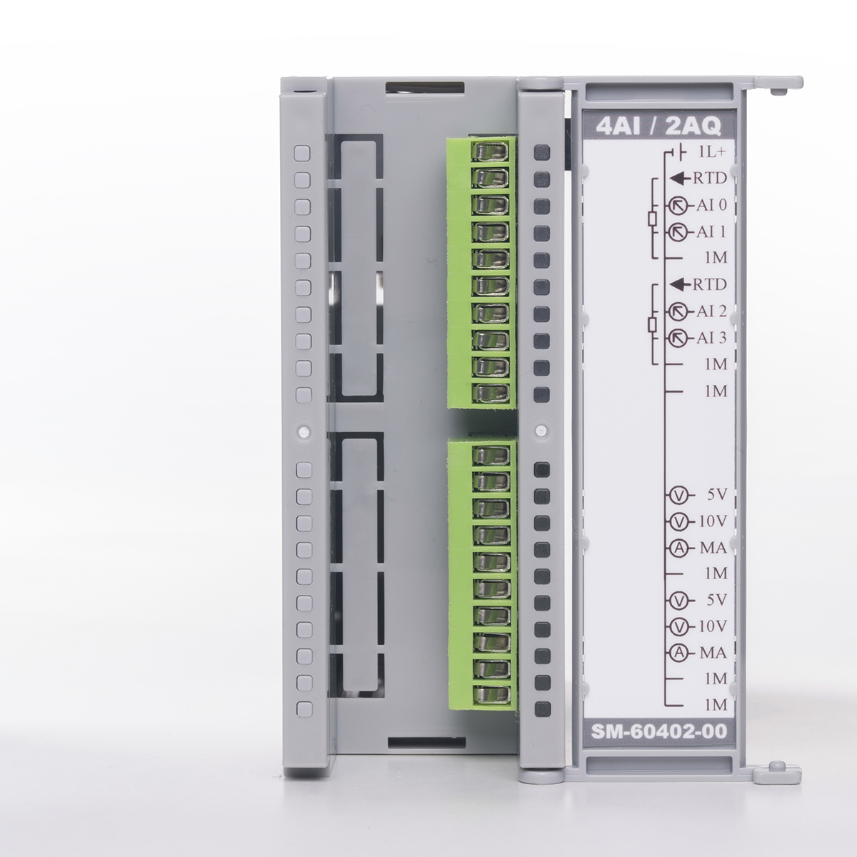 |
150 |
| 4AI / 2AQ 16B. | SM-60402-20-00 | 4 channel 16 bit analog input (2 channels when Pt100, PT1000 and Resistor) and 2 channels 16 bit analog output module. Analog input signal types: 0-10 V. / 0-20 MA. / PT100 / PT1000 / Resistor / Thermocouple B, E, J, K, N, R, S, T. Each analog output channel have three outputs 0-5 V / 0-10 V / 0-20 Ma. All outputs can be used at the same time. The maximum current for voltage output channels is max. 20 Ma. 1000 samples per second. | 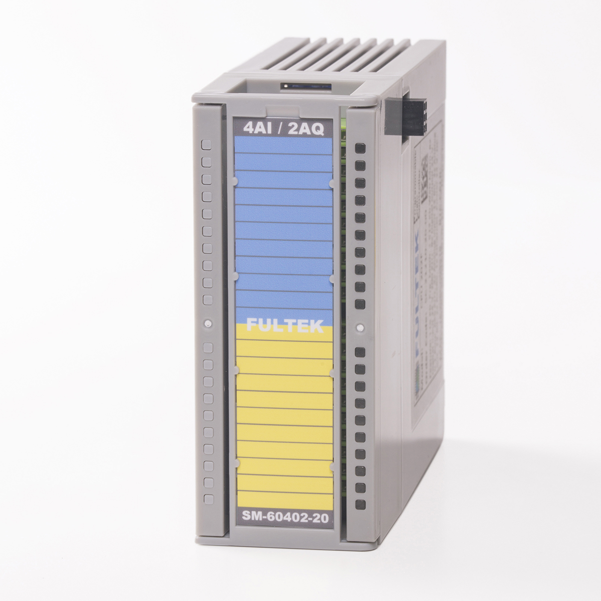 |
 |
170 |
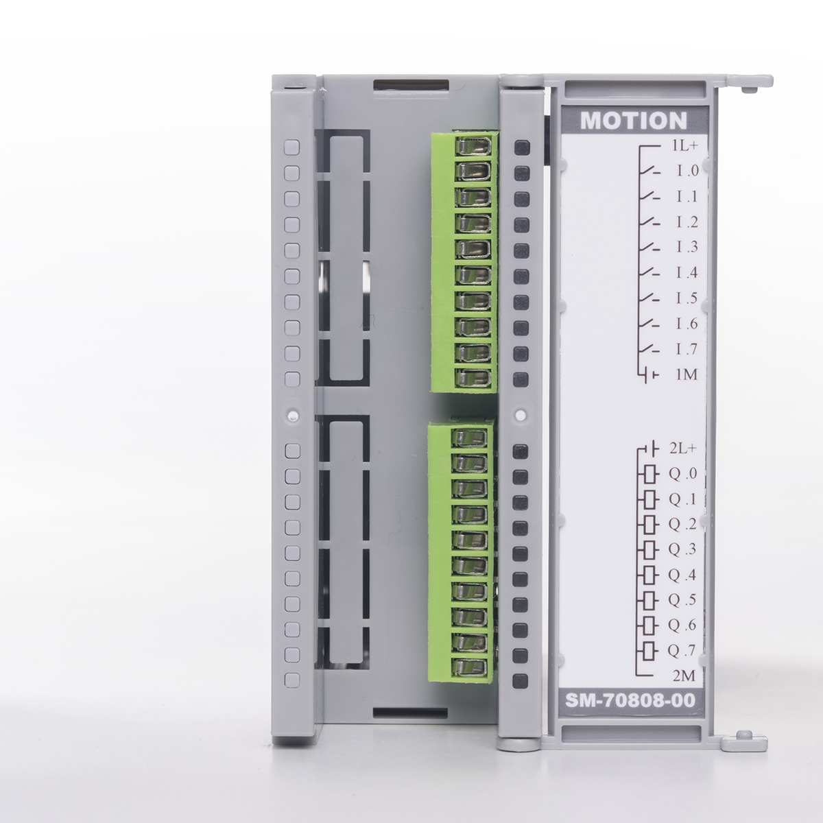
| MOTION | SM-70808-00-00 | 8 channel galvanic isolated digital input and 8 channel galvanic isolated digital output module. DIGITAL INPUTS: Maximum frequency single channel 120 Khz., Two channels 100 Khz, three channels 80 Khz, eight channels 45 Khz. Measurement Type: Counter rising edge, falling edge. Encoder: AB, ABZ, 2X and 4X. Frequency measurement and period measurement. DIGITAL OUTPUTS: Digital output, PWM 655 Khz and PTO. When the selected PTO one channel or two channels in the same group 100 Khz, two channels or four channels in the two group 70 Khz, all outputs 40 Khz. Output current 0.1 Amp. | 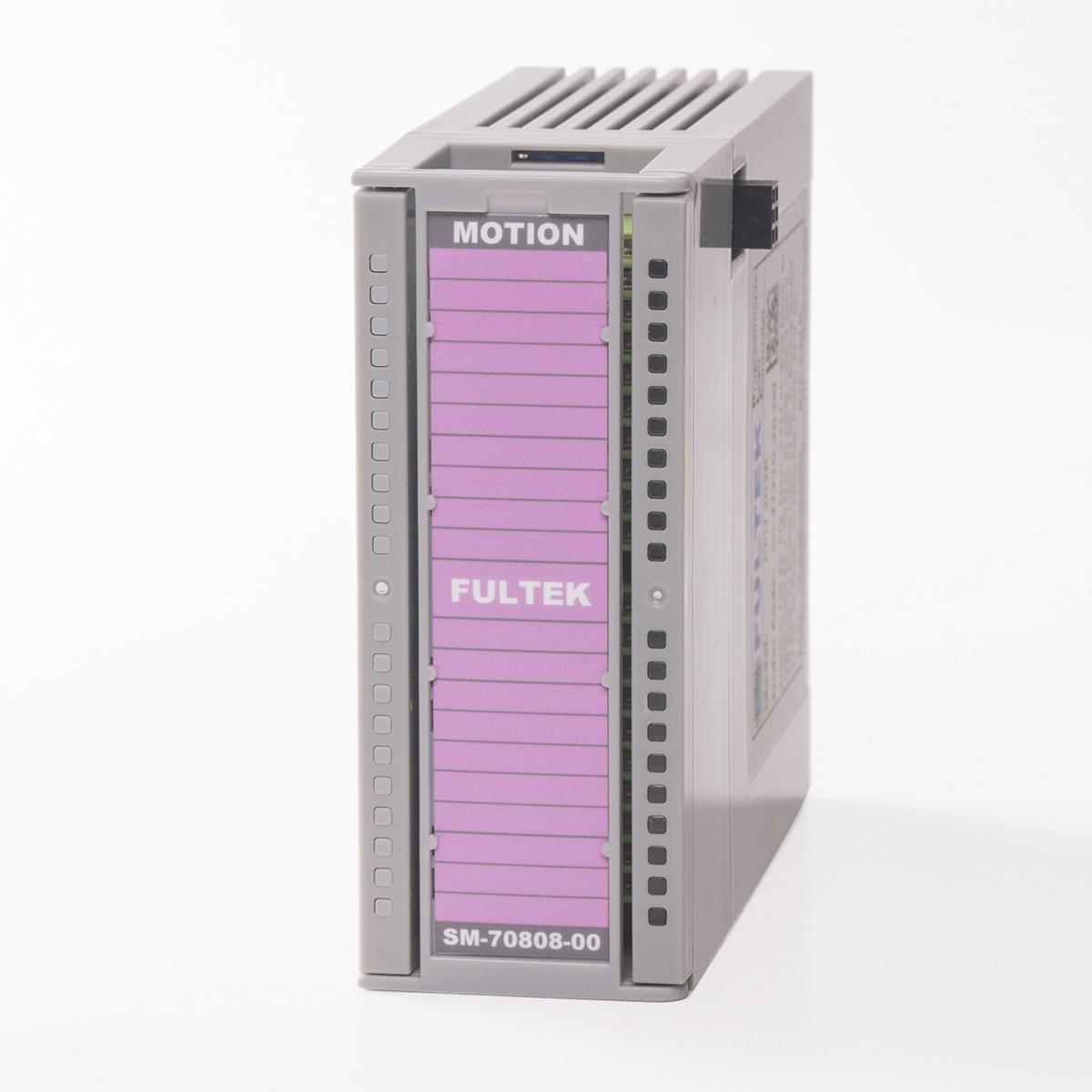 |
 |
200 |
| CP 100 | SM-80202-00-00 | 2 Channel RS485 / RS422 communication module. Maximum 1 Mps. | 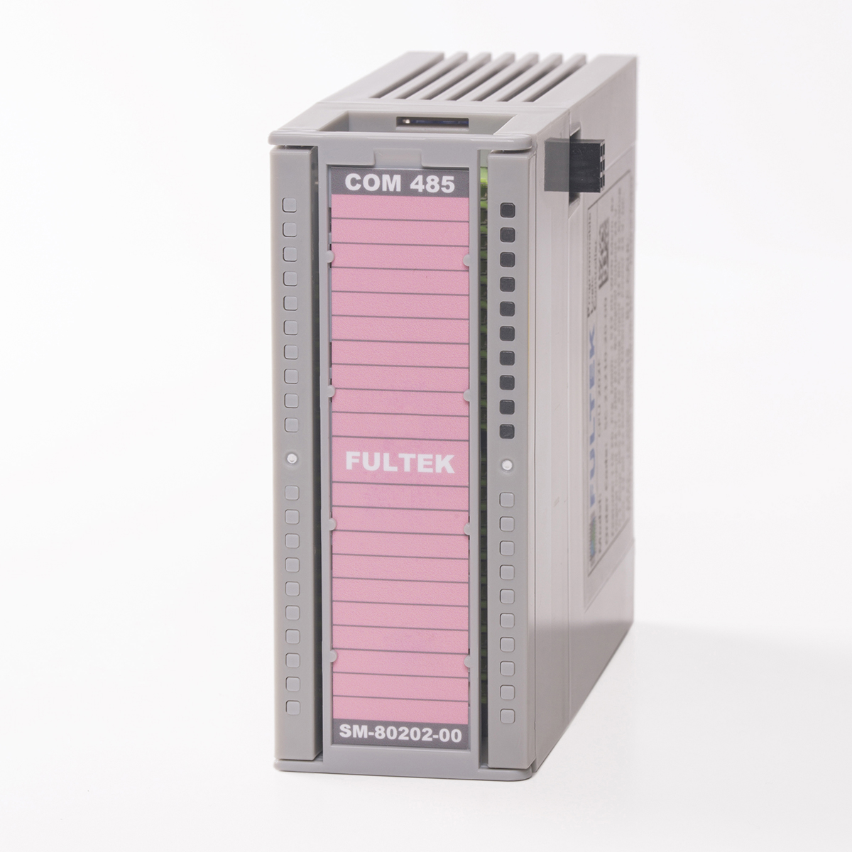 |
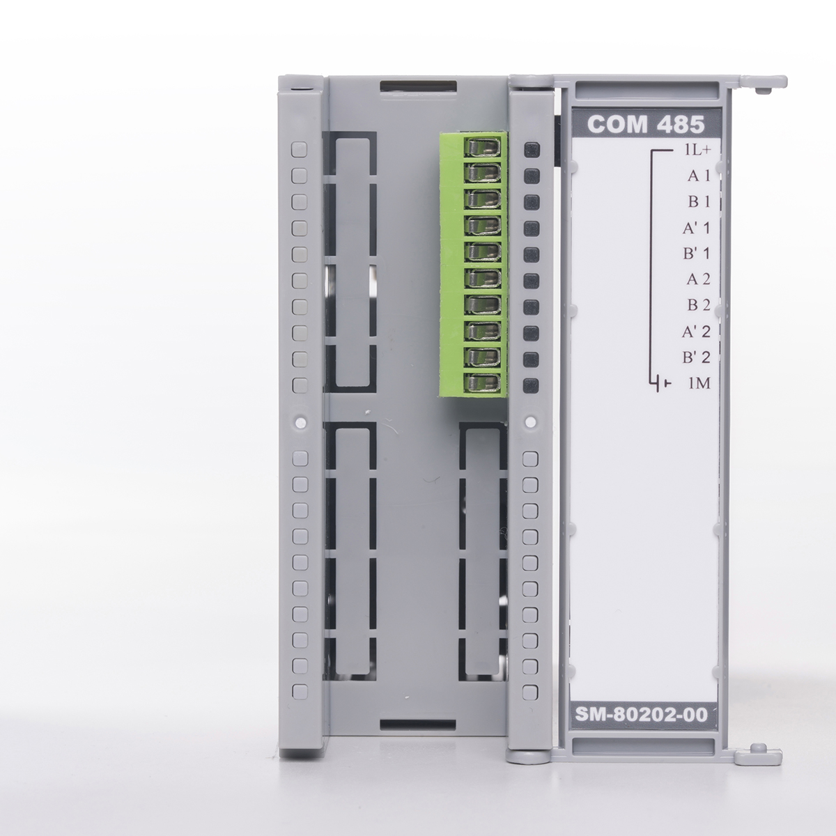 |
200 |
| CP 101 | SM-80202-20-00 | 2 Channel RS232 communication module. Maximum 250 Kps. | 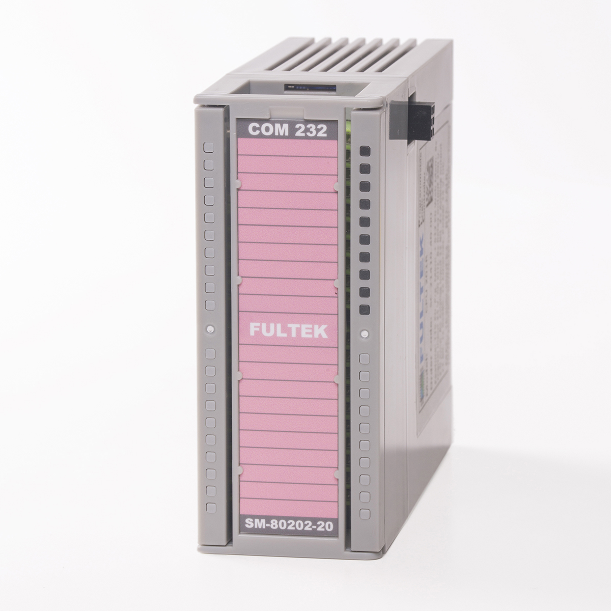 |
 |
200 |
| RACK EXT. | SM-80000-00-00 SM-80001-00-00 | Rack extension module. It consists of two modules, Rack input and Rack output. The rack input module must be installed at the end of the top row rack and the Rack output module at the top of the bottom row rack. The transition cable is standard 100 cm. | 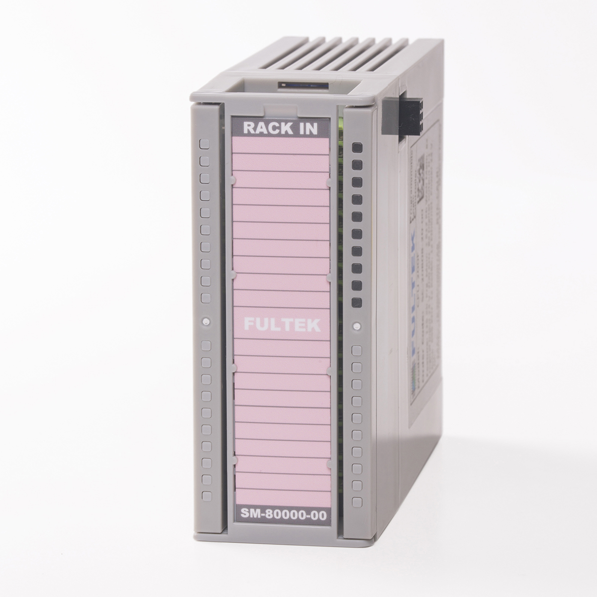 |
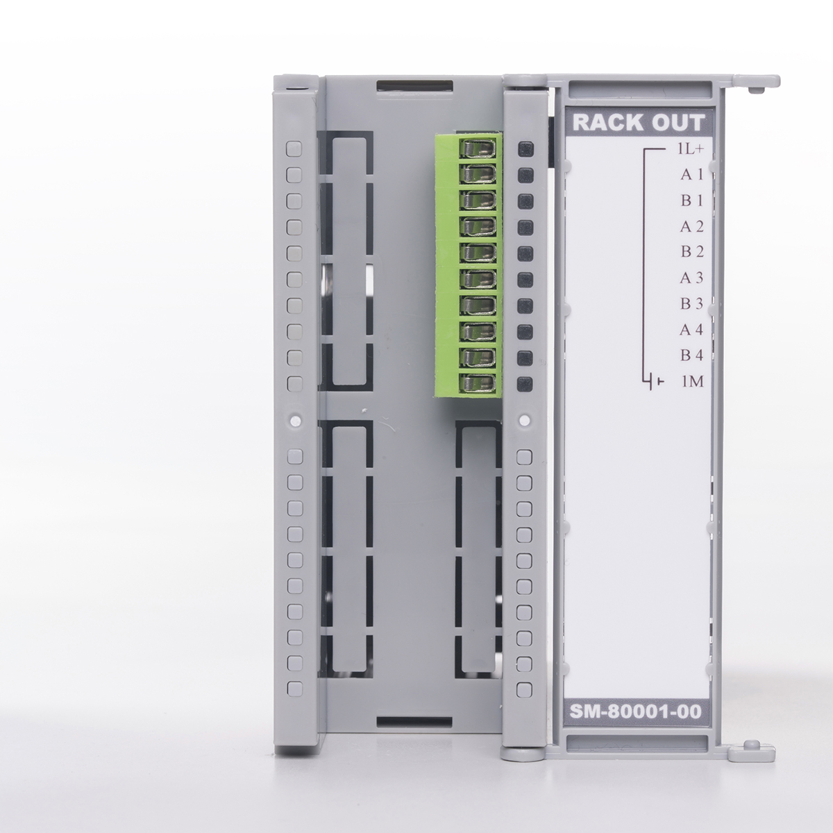 |
200 |